152 Robot
This TV is tailored for the 152 engineering class. This page will describe the steps of designing and fabricating a vacuum formed shell for the 152 robot. This page will also contain links to sign up for the equipment training necessary for completing this training venture and 152 in general.
Necessary Equipment
For 152, students will need to certify on the Soldering Irons, the Electronics Workstation, the Vinyl Cutter, the Vacuum Former, and the Finishing Room. Because the Vacuum Former is located in the Vault, students will also need to pass The Vault quiz as well. Please read the wiki pages and pass the Canvas quizzes for these 6 pieces of equipment/facilities before conducting your in-person demonstrations.
Signing Up for Training/Demonstrations
Given the large number of students in 152, training and demonstrations will follow a similar format to 151.
- Soldering Iron training will be conducted in 4 2-person teams (for a total of 8 students). Ideally, your teammate will be the same teammate you have for the robot project overall. Each 2-person team will solder one Maker Hub LED board kit in a 1-hour block.
- Electronic Workstation training will be conducted in groups of 8 students in a 1-hour block.
- Vinyl Cutter training will be conducted in groups of 8 students in a 1-hour block.
- Vacuum Former and Finishing Room training will be conducted simultaneously within a 1-hour block. This training will also accommodate 8 students at a time.
Please sign up for training at the following Google Sheet:
https://docs.google.com/spreadsheets/d/1BwhbqF90DvTv4_sZq3c2Y9d1rvjpHUb6BeC_hYj_wVU/edit?usp=sharing
Procedure
The following procedure will show the process of vacuum forming and painting/decorating a PETG shell for a 152 robot. There are many ways to shape, paint, decorate, and customize your vacuum formed shell. The examples given in this training venture are intended to demonstrate some of the possibilities for how you might design and build your own vacuum formed shell. You are encouraged to use these examples as stepping stones to build even more creative and inspiring shells for your robot. Just make sure your final product is GFU appropriate.
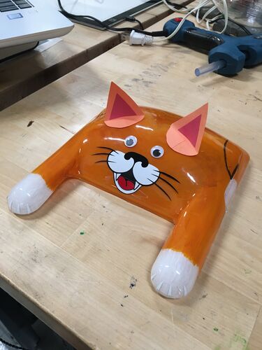
In the example of the orange cat shell at the top of this page, I designed and 3D printed a mold for the shape. After cutting away the excess PETG plastic, I hand-painted the inside of the shell. I used stacked vinyl cutouts for the nose, mouth, and whiskers. I cut white vinyl pieces for the claws. Finally, I added the construction paper ears and googly eyes as the finishing touches. (My orange cat at home--which was the inspiration for this build--has no tail... just in case you were wondering why there's no tail)
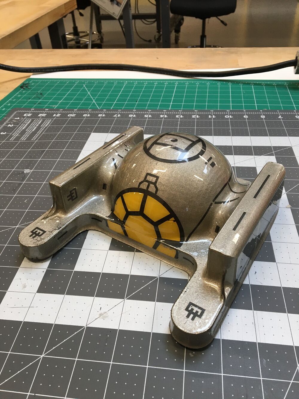
But now we will pivot, and I will explain a second example robot shell in greater detail with pictures to show you the process. This robot shell was modeled after Darth Vader's tie fighter.
There are several modular mold pieces that you can use to create the general shape of your robot's shell. Ask one of the 152 TAs where these modular mold pieces will be kept. You are encouraged to add extra 3D printed parts or wooden pieces or create your own custom shape for your shell. Keep in mind that the vacuum former has limits for how far you can draw down the heated plastic before it rips or begins webbing. For example, don't expect to vacuum form a 6-inch cube cleanly with zero webbing. There are creative ways to minimize webbing or stack two vacuum forms together, but this will be part of your creative discovery of how vacuum forming works.
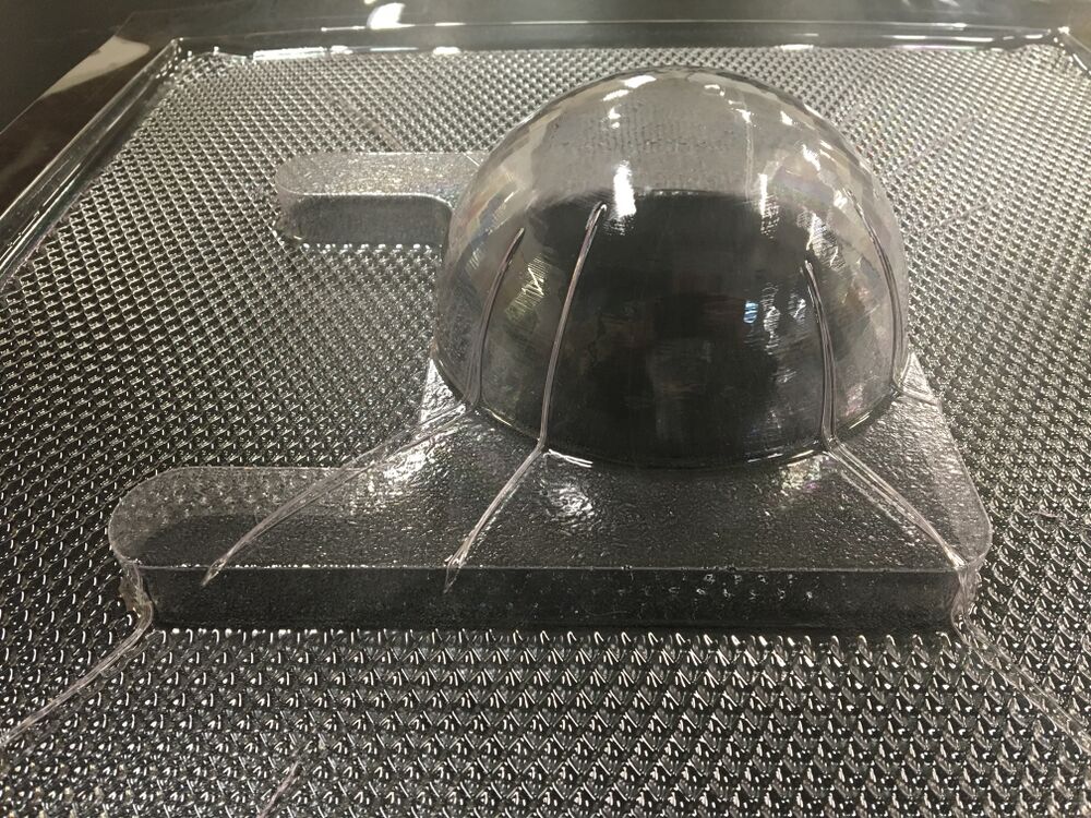
What is webbing? See the following image. Webbing refers to the creases that form in the heated plastic as a result of internal stresses as the plastic is stretched over a mold. Webbing is more likely to occur if the plastic is overheated.
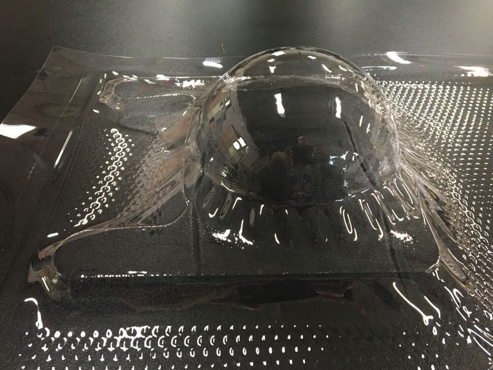
By contrast, the following image shows what happens if the plastic is underheated. Underheated plastic will not draw down enough to form the shape you are intending. Turns out that this particular shape was more difficult than expected.
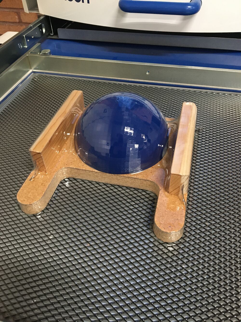
The following image shows the mold I used to attempt the shape of Darth Vader's tie fighter. I used the dome-shaped 3D print mold in conjunction with a scrap piece of wood that I cut in half and modified in the wood shop. Notice that after vacuum forming, the plastic did not draw down all the way between the dome and the two wood pieces.
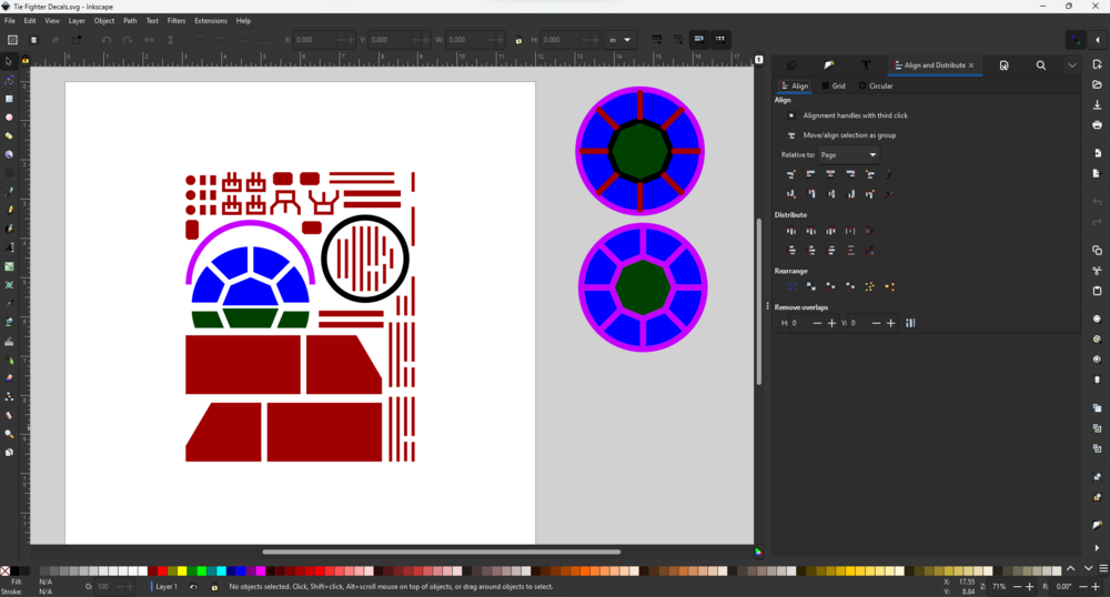
I drew several shapes in Inkscape that would compose the features of the tie fighter. These shapes would be cut out of a scrap piece of vinyl on the vinyl cutter and act as a mask while spray painting later in the process.
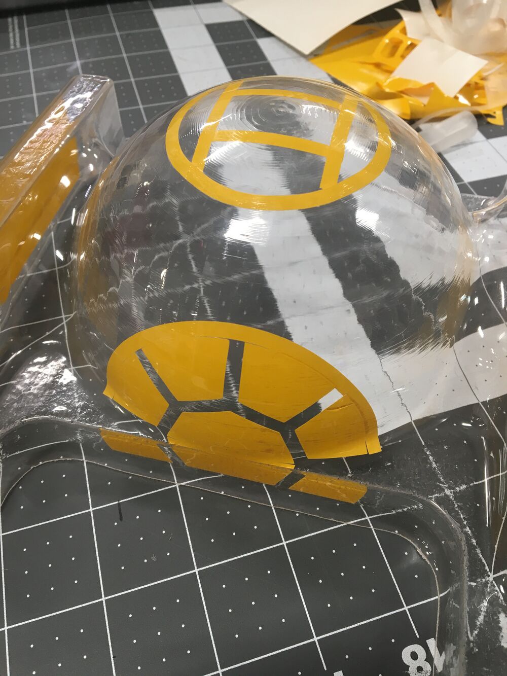
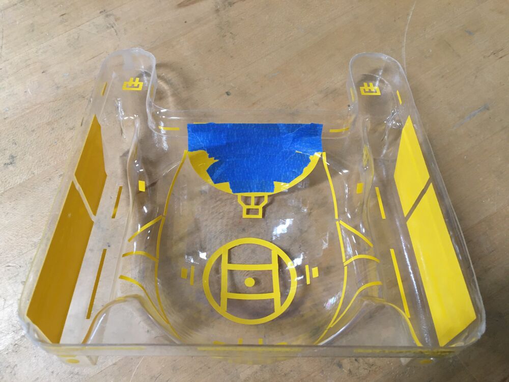
After cutting away the excess plastic and smoothing the edges of the shell, I began applying the vinyl pieces to the inside of the shell.
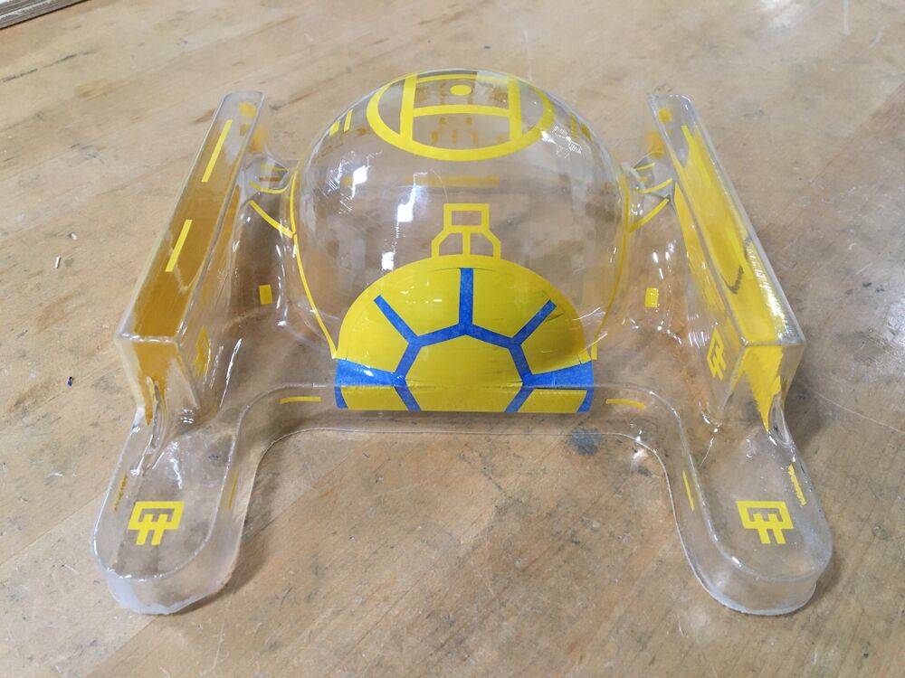
Further along in the vinyl application... I applied painter's tape on top of the vinyl around the tie fighter's cockpit. The goal here is to have the windows of the cockpit be see-through after spray painting.
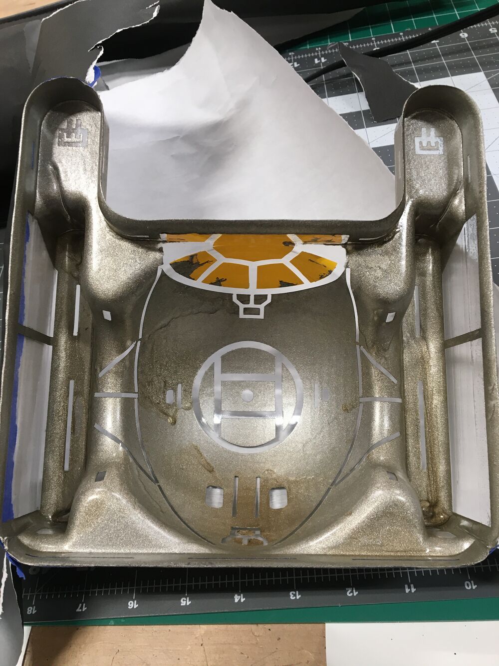
Here's an inside view of all the vinyl plus the painter's tape.
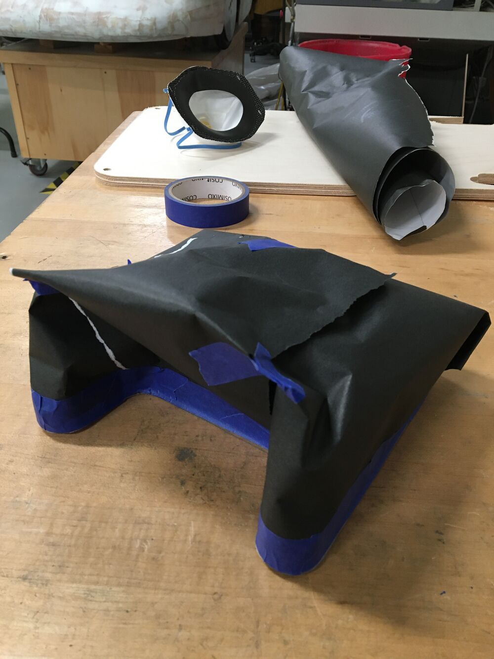
Next, I used some paper and painter's tape to mask off the outside of the robot shell because I did not want any spray paint getting on the shell's exterior.
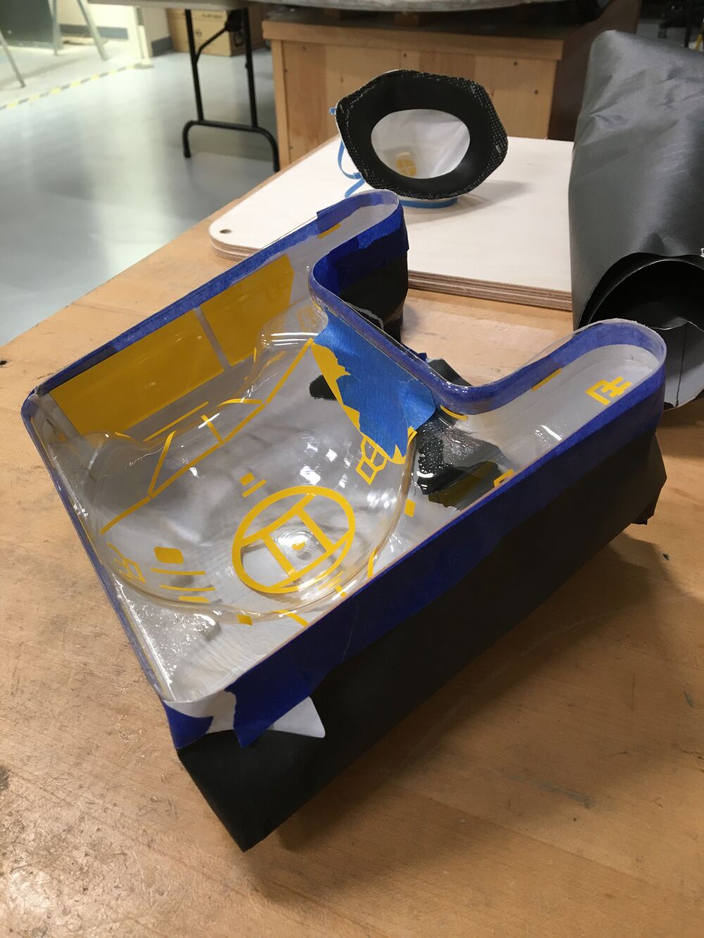
Here's a view of the underside/inside with the exterior spray painting mask in place.
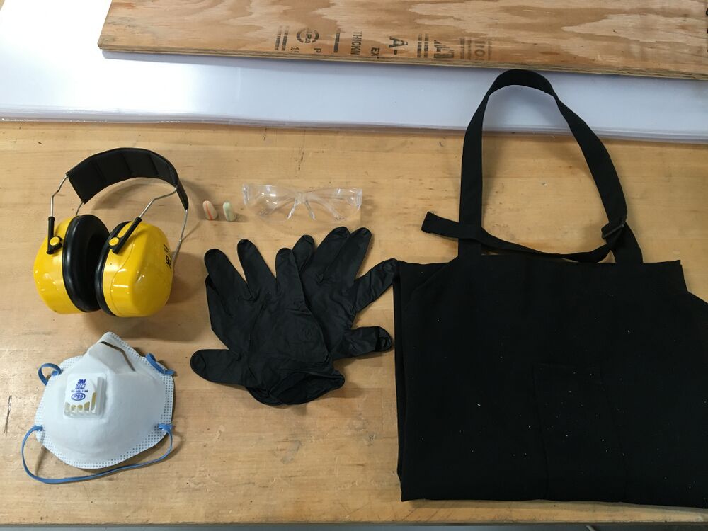
To prepare for spray painting in the Finishing Room, here's the PPE (personal protective equipment) that you must don before starting. You will need safety glasses, hearing protection (either ear plugs or the over-the-ear style), nitrile gloves, and a P95 mask. Ear plugs and nitrile gloves are located at the safety station by the Wood Shop door. The over-the-ear style hearing protection are located on top of the CNC router terminal in the Wood Shop; please return them to that same location if you use them. To obtain a P95 mask, please ask one of the Tool Room attendants to provide you one from the Tool Room inventory. If the Tool Room is closed, ask one of the Maker Hub staff to retrieve a P95 mask for you from the Tool Room. Make sure that you use a P95 mask when spray painting. There are both P95 and N95 masks available from the Tool Room, but N95 masks are only designed to protect against non-oil-based particles inhalation (e.g. dust), not oil-based particles (e.g. paint fumes). Ensure you are using the correct mask--a P95--for spray painting. And finally, the apron is optional if you want to reduce the chances of getting paint on your clothes. The aprons are located on the back corner of the low fidelity prototyping station.
My first round of spray painting was a metallic gray. As you can see, I was a little heavy-handed and impatient with the spray paint which resulted in drips and pooling. Best practices with spray paint almost always call for thin, light coats for best results. Some of the internal topography of my shell proved quite difficult to reach with the spray paint stream which contributed to the drips/pooling. Luckily, the drips and pooling aren't really visible from the outside of the shell, so it turned out ok. I ended up applying two coats of the metallic gray. After the paint dried, I removed the vinyl masking and the painter's tape around the cockpit. However, I left the vinyl masking for the windows in place. I used Q-tips and isopropyl alcohol to clean up any stray paint that got behind the vinyl mask.
My second round of spray painting was a matte black. I applied two coats of the matte black on top of the dried metallic gray paint. Because I removed all of the vinyl masking after the round of metallic gray spray paint, all of the places where I originally put the yellow vinyl masking would now end up black to outline the features of the tie fighter.
After the matte black paint dried, I removed the final vinyl mask for the cockpit windows. Again, I used Q-tips and isopropyl alcohol to clean up any stray paint that got behind the vinyl mask. And voila! We have created a passing resemblance of Darth Vader's tie fighter. Now all we need is Darth Vader himself...
Attaching the Shell to the Chassis
Now, you may be wondering how to attach your masterpiece robot shell to the chassis. Below are two SolidWorks files that can serve as a starting point for connecting the shell to the chassis in a manner that is easily removable. I make no claims that this is the best design by any stretch. In fact, I hope that the 152 students can use their CAD skills from 151 to come up with a better design and share it here for the benefit of their classmates.
152 Clip 5 M.sldprt
152 Clip 5 F.sldprt
These two parts are designed to be 3D printed.
