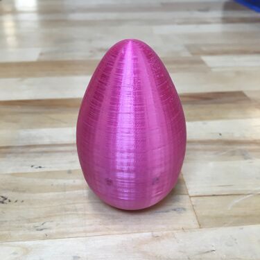
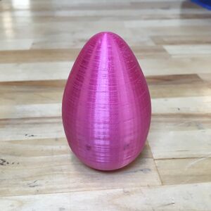
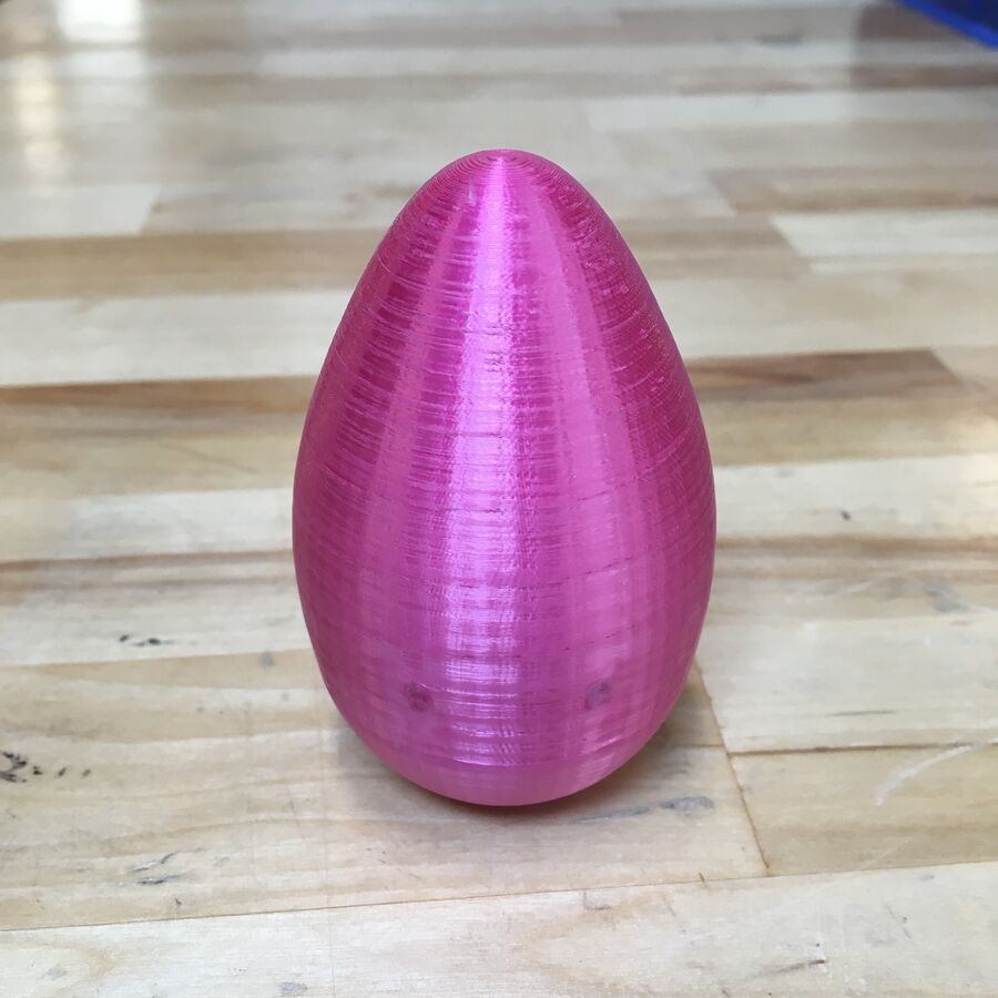
Egg Shaker
In this TV, we will take you through the steps of designing an egg shaker in SolidWorks, preparing the print in PrusaSlicer, and then 3D printing it using the Prusa 3D Printer.
Procedure
Buckle up...
SolidWorks
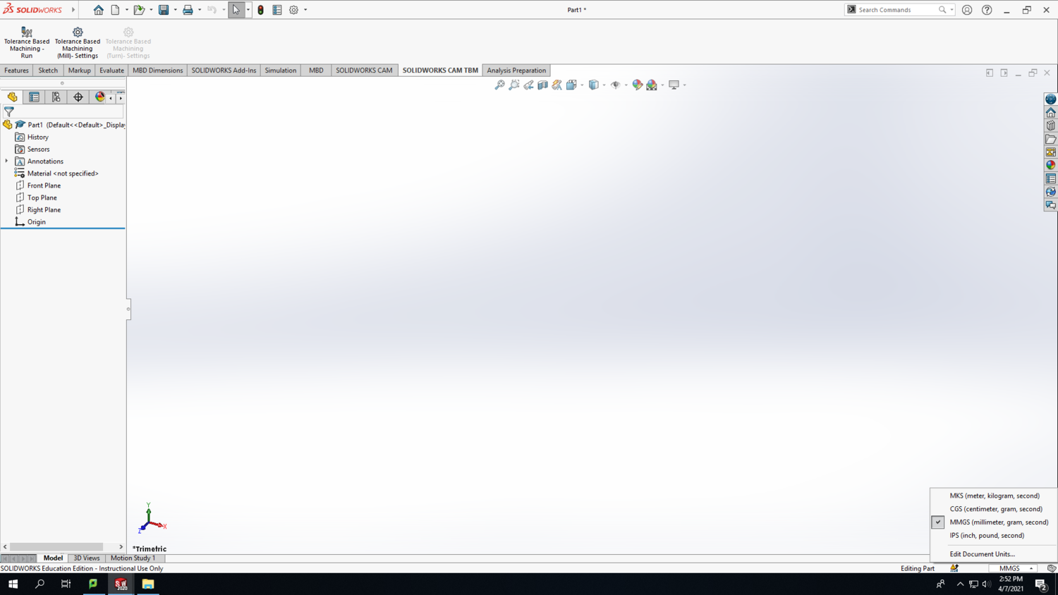
Step 1: Open SolidWorks 2020, and select a new part. Don't forget to save your file frequently as you go. In the bottom-right corner of your Solidworks window, change the units to MMGS (millimeter, gram, second).
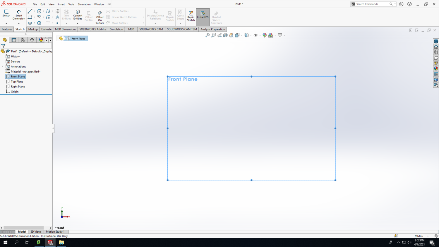
Step 2: Select the Front Plane in the design tree (the left column on your screen) to begin your sketch. Click on the Sketch tab above and click Sketch.
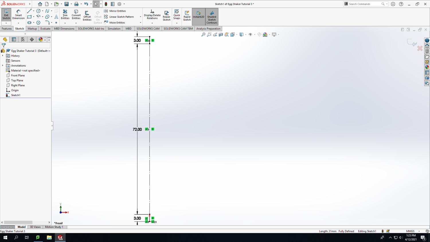
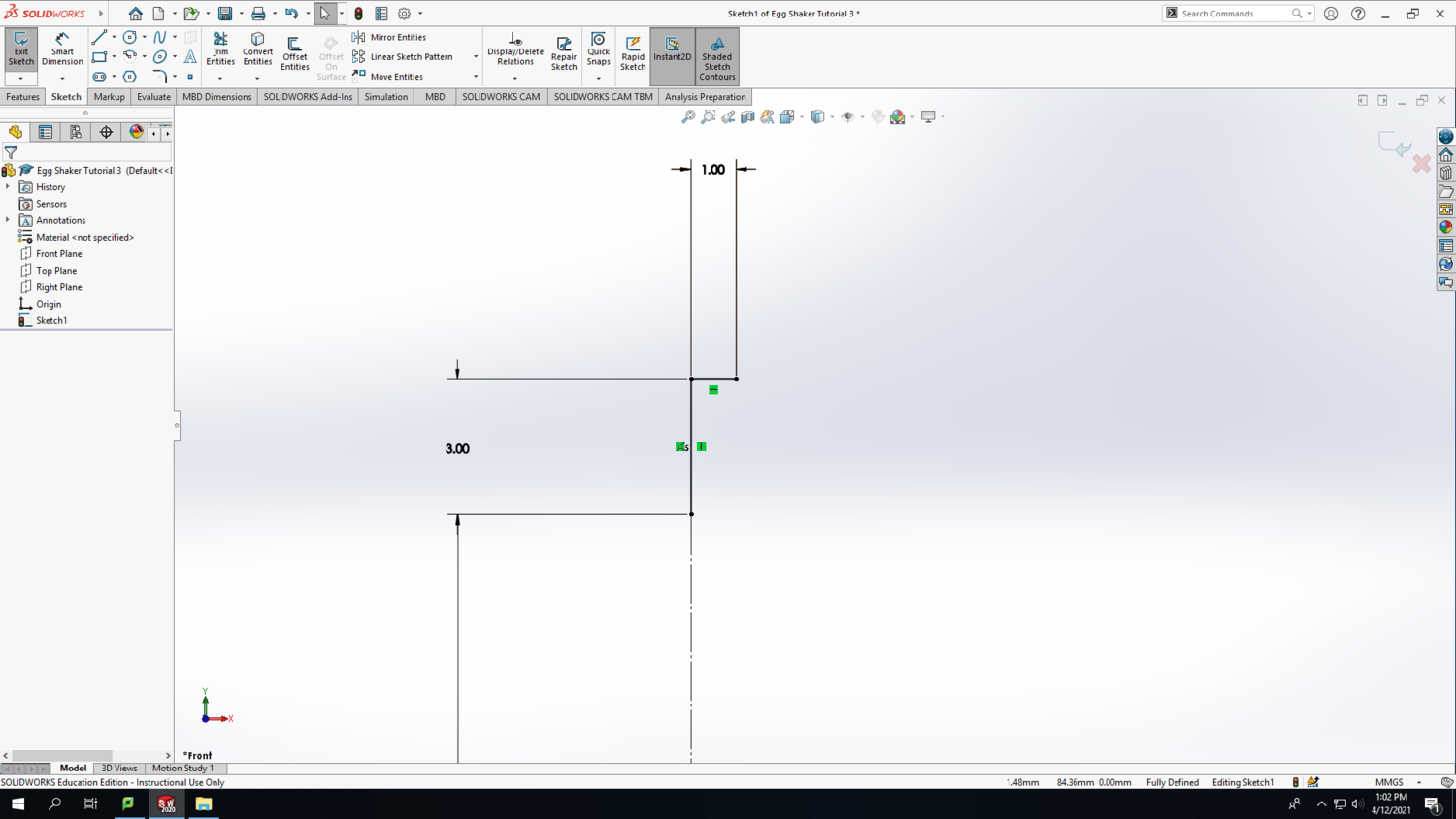
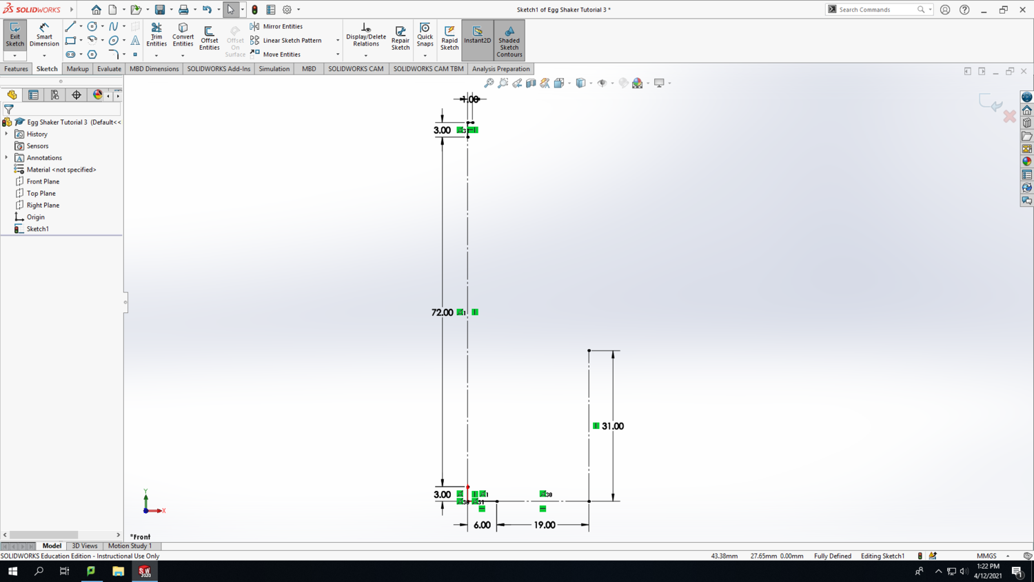
Step 3: Make a vertical line starting from the origin. Then use the smart dimension tool to make it 3mm tall. Follow the same process to draw 2 more lines stacked on top of one another, and make them the lengths shown in the screenshot below. Make the inner line a construction line by clicking on it (after exiting the Smart Dimension tool) and hovering over the icons until you find the "Construction Geometry" icon. After clicking it, the line will become dashed.
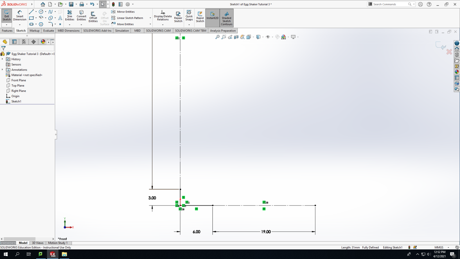
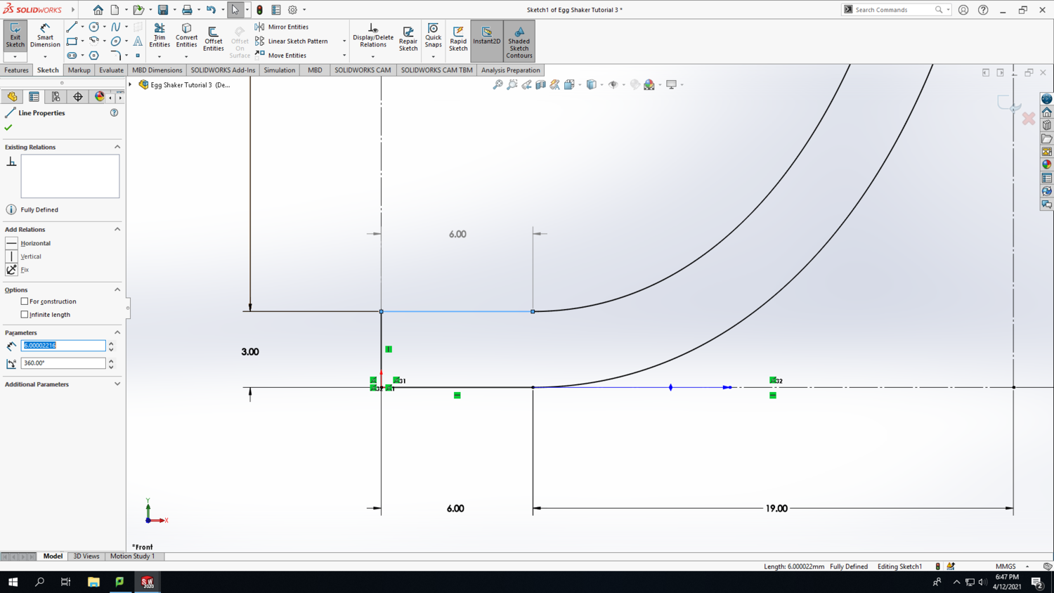
Step 4: Make a horizontal line starting from the origin. Then use the smart dimension tool to make it 6mm long. Draw another horizontal line next to it with the length shown in the screenshot below. Make the second line a construction line by clicking on it (after exiting the Smart Dimension tool) and hovering over the icons until you find the "Construction Geometry" icon. After clicking it, the line will become dashed.
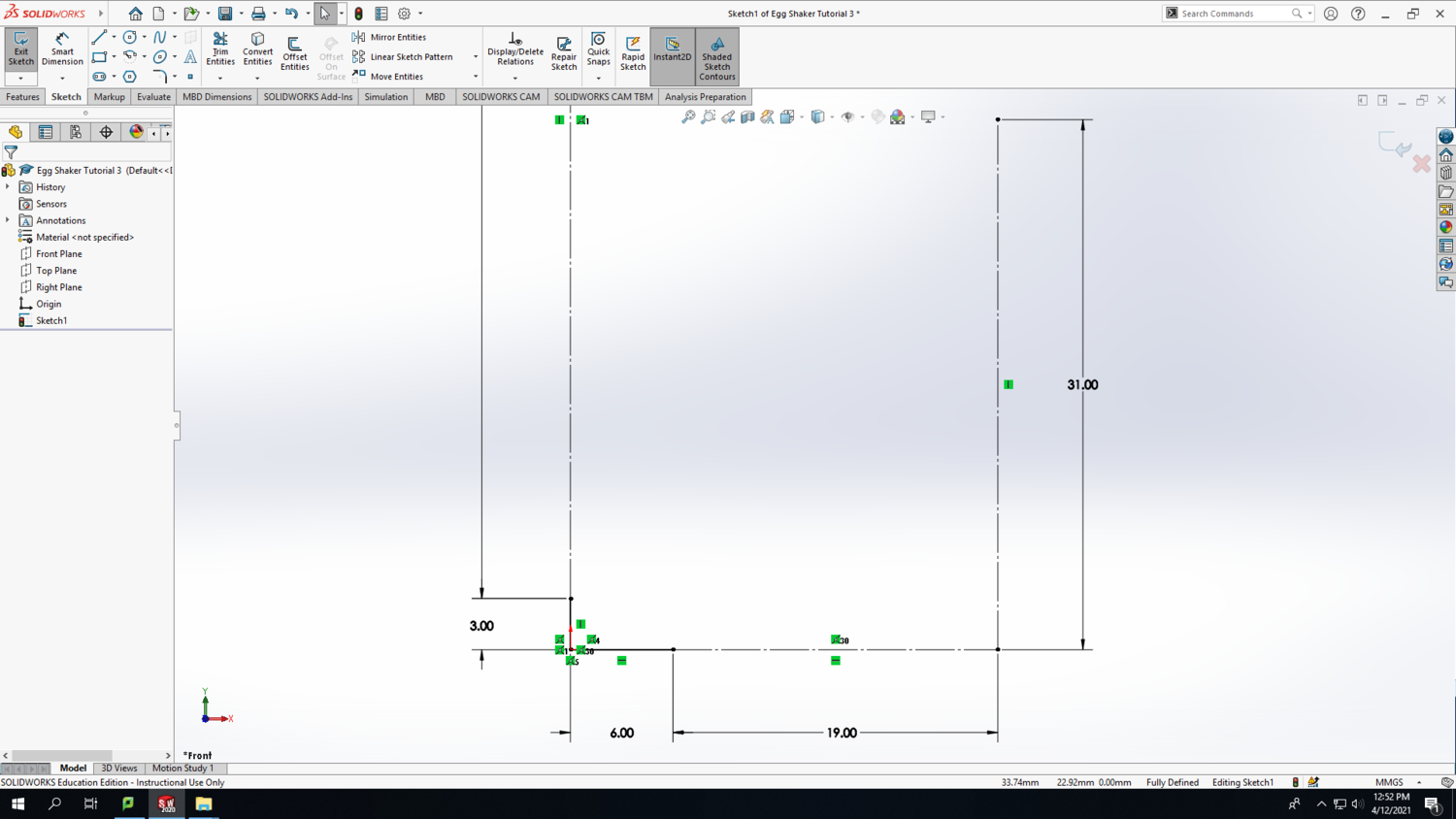
Step 5: From the right end point of the horizontal construction line, draw a vertical construction line with the length shown in the screenshot below.
Step 6: At the top of your sketch, draw a 1mm horizontal line at the location shown in the screenshot below.
Step 7: At this point, you should have a total of 4 solid lines and 3 construction lines that look like the screenshot below.
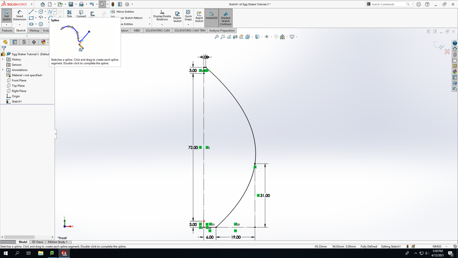
Step 8: Use the spline feature to connect 3 points on your sketch and create a side profile of your egg. Order does matter, so click sequentially from top to bottom or bottom to top on each of the 3 points. Press Esc to finish the spline. You'll notice that it doesn't really look like the side profile of an egg yet, but we'll fix that shortly.
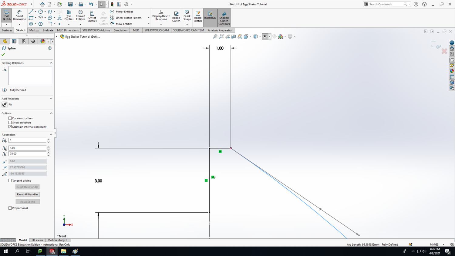
Step 9: Now, you are encouraged to use your creativity to tweak the side profile of the egg to your own taste. I'll give a couple suggestions for how to tweak the spline for best results, but you are welcome to change the lengths of any of the construction lines to get different results. When you have the spline selected, you will see "adjustment arrows with diamonds" that are tangent to the spline. They can be manipulated to change the shape of the curve. Click and drag the diamond to change the angle; click and drag the arrowhead to change the length; click and drag the point at the tip of the arrowhead to simultaneously change both the angle and the length. You always can press ctrl-Z to undo a change and revert back to the spline's previous shape.
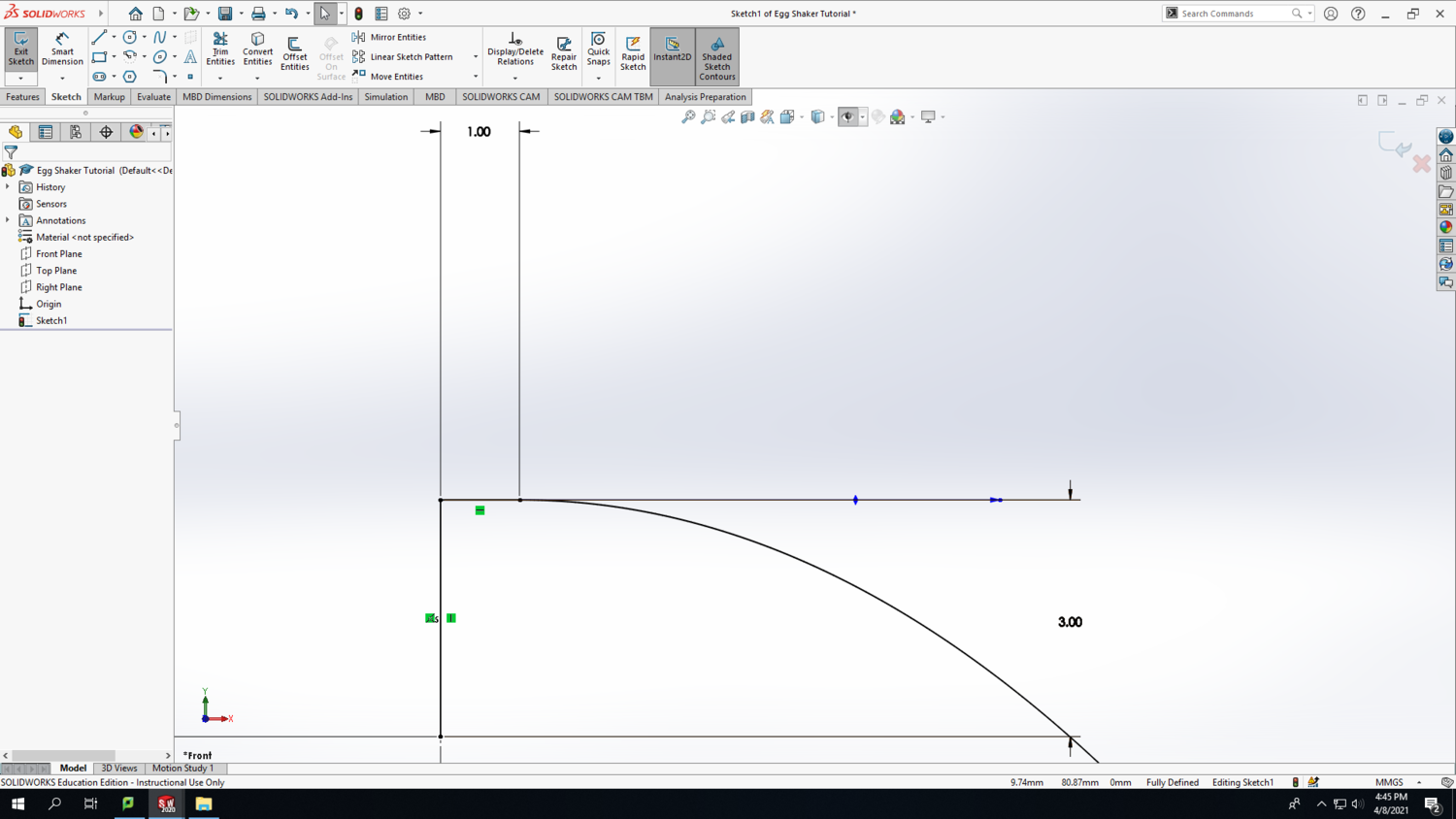
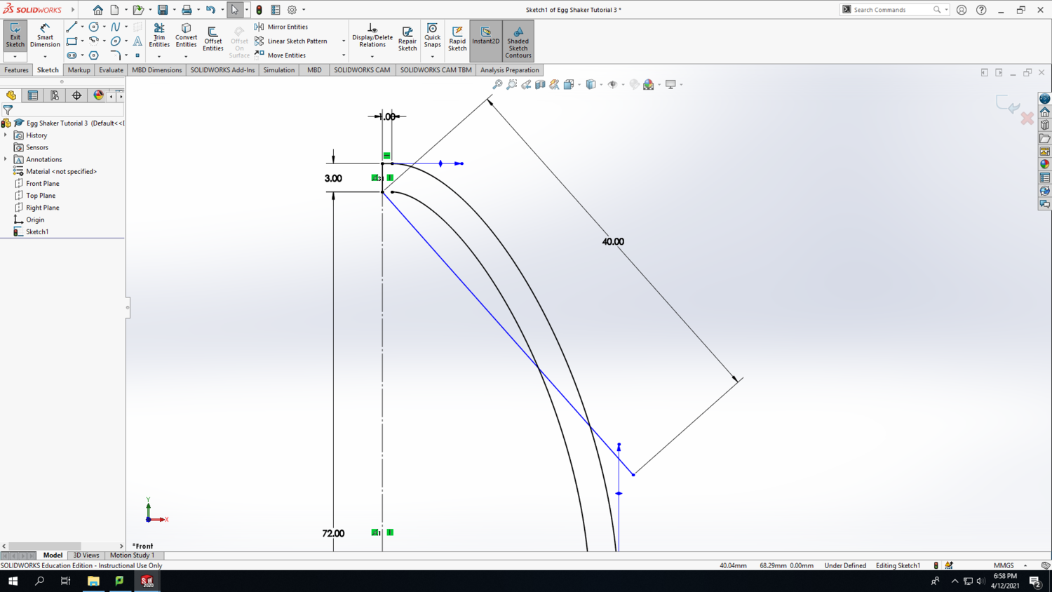
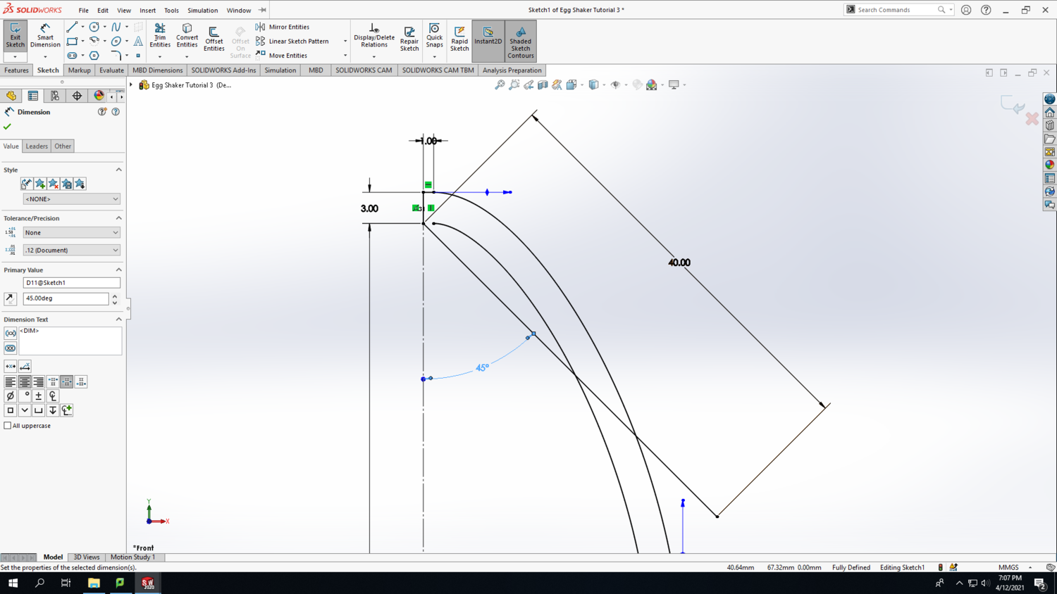
If you zoom into the top of the egg, you'll notice that the spline connects to the 1mm horizontal line at an angle (see the first screenshot). We would like the spline to be approximately horizontal at the point of connection with the 1mm line. This will give the appearance of a nice continuous curve, but it doesn't need to be exact. To do that, pull the Smart Dimension of the 3mm line over to the right side to give yourself a reference. Then move the adjustment arrow thing from the spine parallel with the Smart Dimension reference line (see the second screenshot).
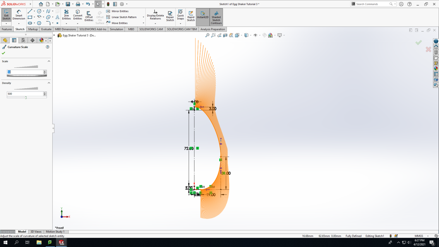
Step 10: Zoom into the bottom of the egg and perform the same operation on the connection between the spline and the 6mm line. Again, the goal is to make the spline approximately horizontal where it connects with the 6mm line to maintain the continuity of the curve. As you manipulate the spline, you might like to click on the Show Curvature checkbox in the left column to see a visual representation of the spline's curve intensity at each point. Change the curvature scale and density to taste.
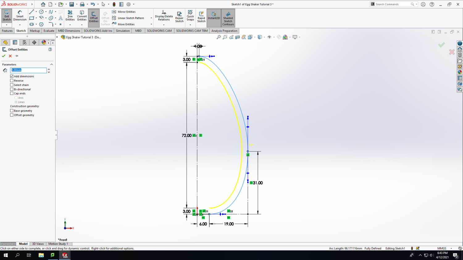
Step 11: Once you are happy with the shape of your spline, you can deselect Show Curvature. Select the spline and click on Offset Entities. Set the distance to 3mm; this is defining the wall thickness of your egg. Make sure the new offset curve is on the inside of your spline. Toggle the Reverse checkbox to switch the offset curve between inside and outside.
Step 12: Connect the offset curve to the vertical 3mm line at the bottom of the egg with a horizontal line.
Step 13: Arbitrarily, draw a diagonal line from the point shown in the first screenshot below and set the length to 40mm long using the Smart Dimension tool. Notice that when you click elsewhere to deselect the line you just drew, it doesn't turn black like the rest of the lines in your sketch. This is because the line is "Under Defined," which is also indicated at the bottom of the SolidWorks screen. To fully define this line, click on the diagonal line and the vertical 72mm construction line using the Smart Dimension tool to set the angle to 45 degrees. The result should look similar to the second screenshot below. Why is this diagonal line necessary? Well, we don't want any supports printed inside of the egg because that would impede the beads/pellets from moving freely to create the egg shaker's signature "shaking" sound. 3D printers don't do a great job printing over thin air with no supporting material underneath. However, most 3D printers can handle a 45 degree incline quite well, and this diagonal line ensures that no surface on the top half of the egg is shallower than 45 degrees with respect to the build plate. This 45 degree line will turn into a cone shape later on. Geometry is one of the most important factors that affects the likelihood of a successful print, and for this particular project, the top part of the egg will present the greatest risk of causing the print to fail.
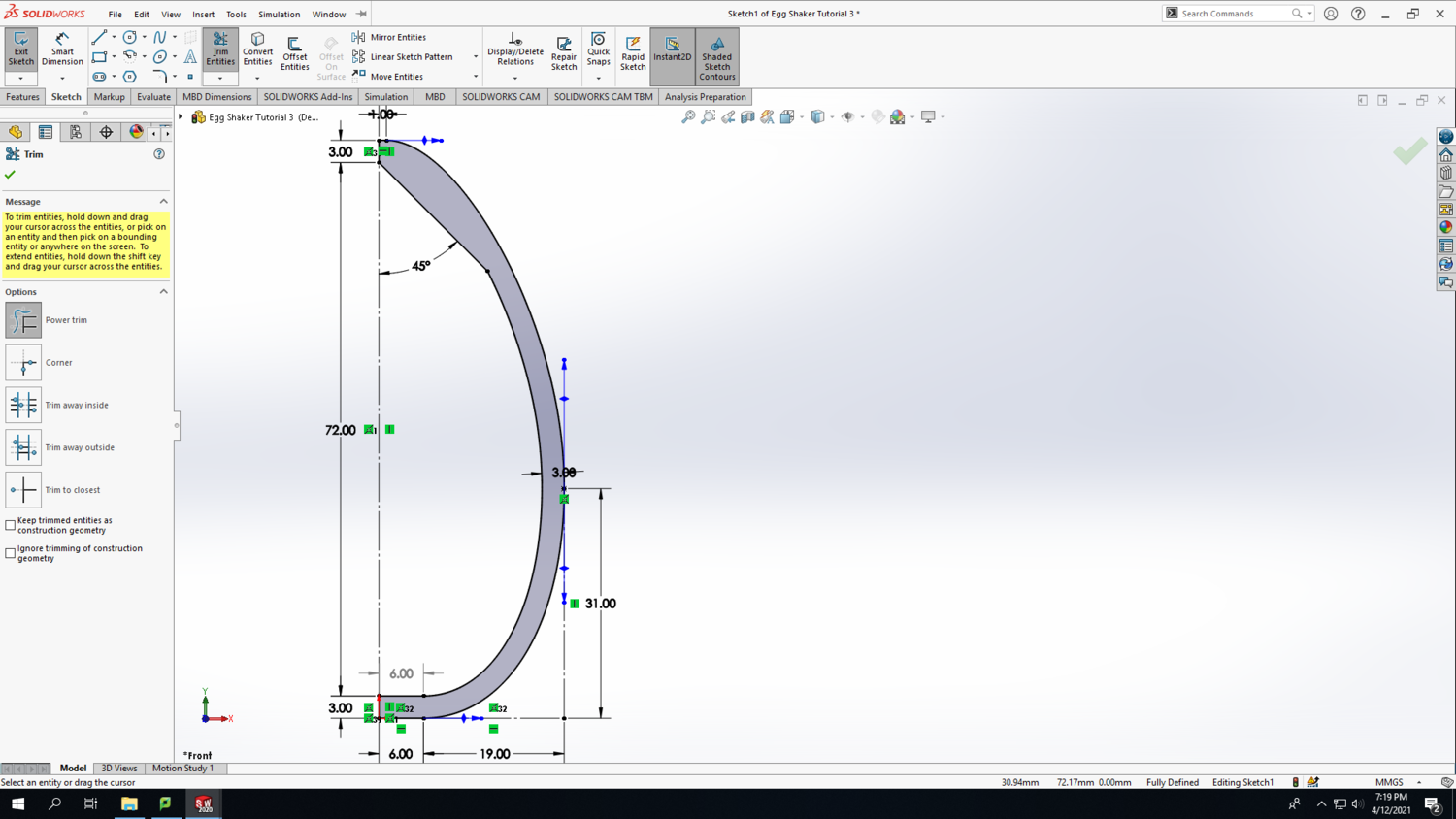
Step 14: Use the Trim Entities tool to get rid of two parts of the diagonal line and part of the offset curve to achieve the shape shown in the screenshot below. The Trim Entities tool functions by clicking and dragging a line across the parts that you want to disappear. The resultant shape should turn grey to indicate that it is a closed area.
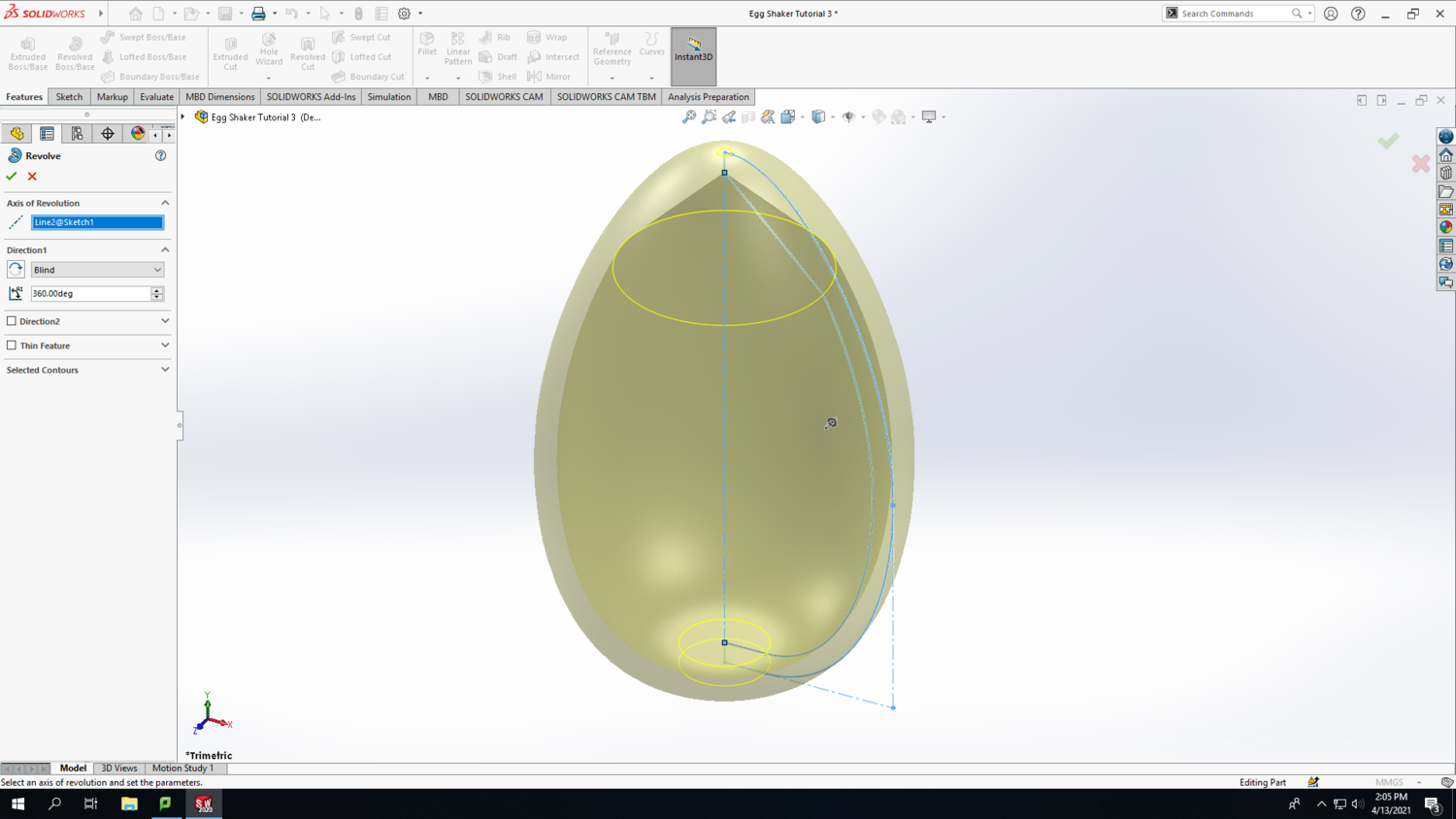
Step 15: Now the fun part begins because we are moving from 2D to 3D. In the top left corner, click Exit Sketch (your sketch should turn light grey). Click on the Features tab and select the Revolved Boss/Base option. SolidWorks may ask you to select a plane to perform this revolve in; click on the 72mm line as the axis of revolution. Usually SolidWorks will figure out the rest of the revolve, but you may have to select the correct contours to get the desired result. Click the green checkmark in the left column if everything looks good. If the revolve function gives you an error, you may have to go back into your sketch and fix something.
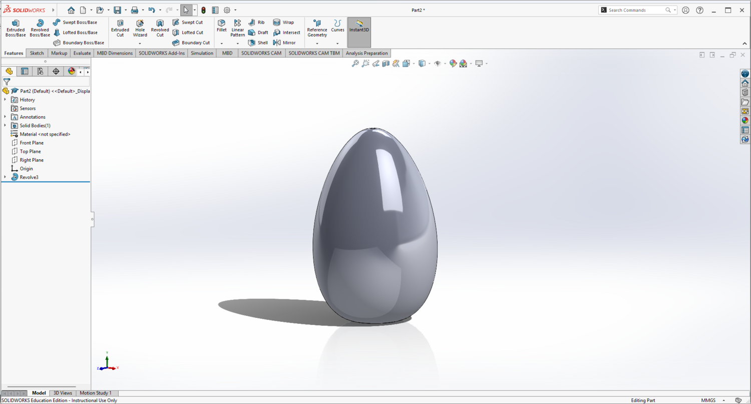
Step 16: You should now have a 3D egg similar to the screenshot below. Save your work! Then press Save As to save your file as a STL (*.stl). You will bring your STL file into the prototype lab to set it up in PrusaSlicer.
PrusaSlicer
Step 16: In the Prototype Lab, open your .stl file in PrusaSlicer. You should look for the following icon.
Step 17: When a .stl file is loaded in PrusaSlicer, the software doesn't always get the orientation of the object correct (as in the first screenshot below). You may need to rotate your egg in order to put it in the correct orientation for 3D printing. You can use either the Rotate function or the Place on face function; both are located in the left-hand toolbar. Rotate the egg to ensure that the bottom of the egg is on the build plate.
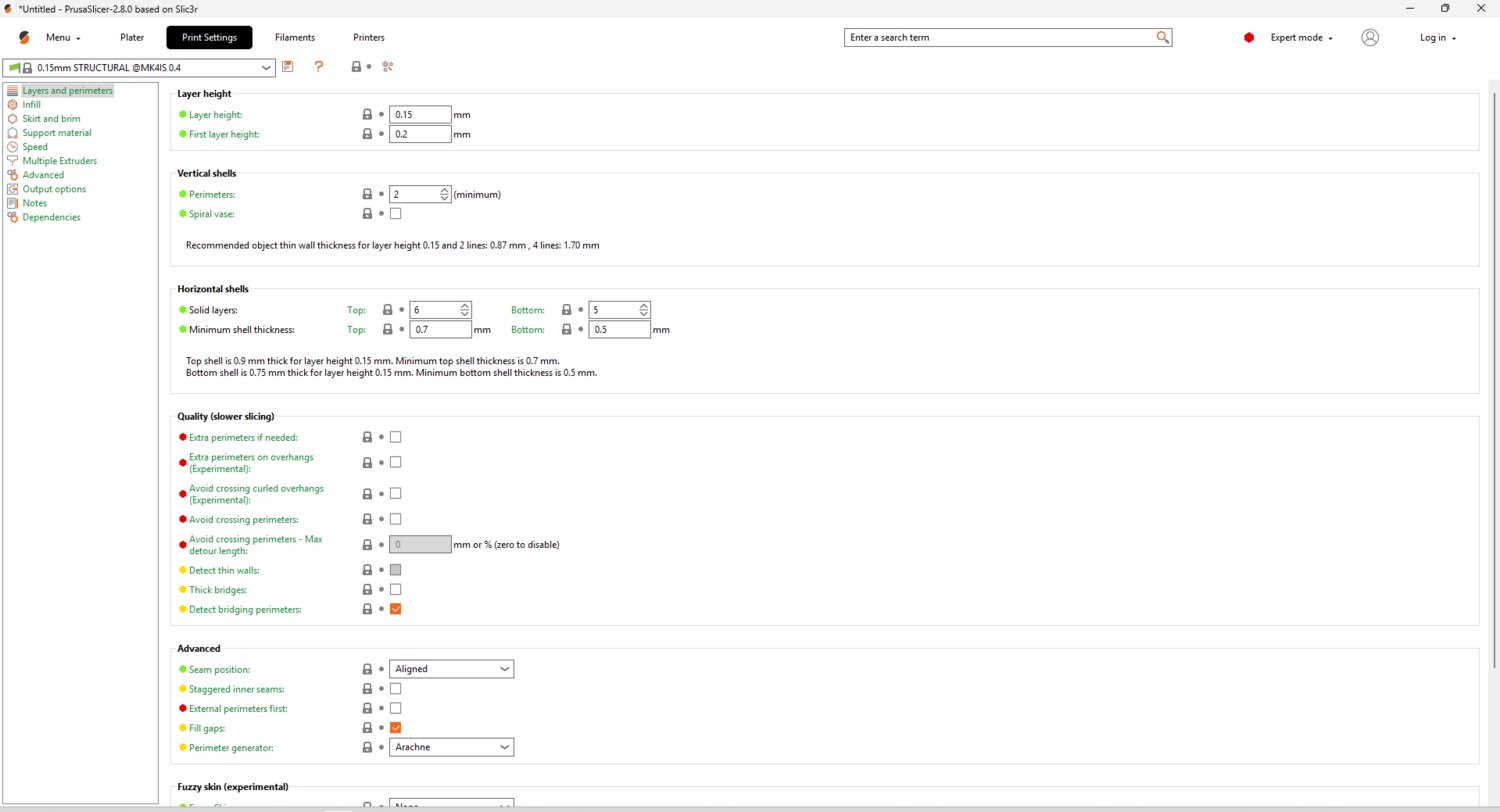
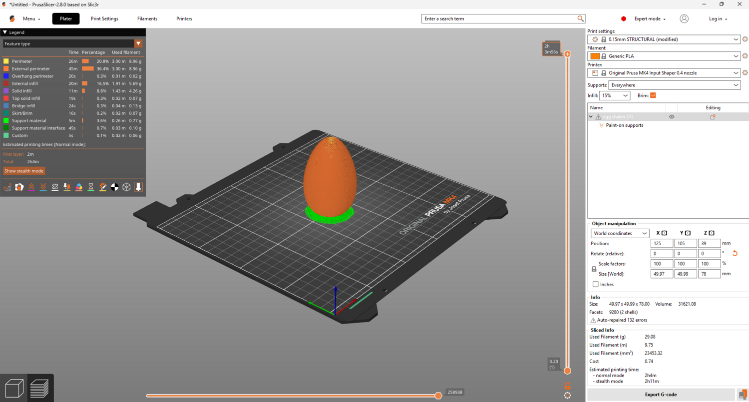
Step 18: Configuring your print settings for a 3D print is often a mix of objective and subjective decisions. Using the "right" print settings can make a big difference in the final quality of your part. Certain print settings may make the part fail entirely. The print settings used in this tutorial work for the 3D printed egg shaker, but they may or may not fall into the category of "general best practices for 3D printing." Disclaimers aside... In the right column, use the three drop-down menus to select: 0.15mm QUALITY and Prusa PLA. Select the correct printer (MK4 or MK4S) based on which printers are available. In the Supports drop-down menu, select Support on build plate only and allow PrusaSlicer to enable the Detect bridging perimeters feature. Set the Infill to 15% and check the Brim box.
Step 19:
Navigate to the Print Settings menu, as seen below.
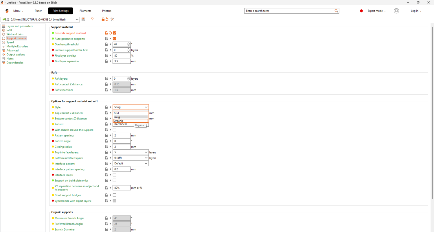
Click on the Support Material menu. Notice that the majority of the options are locked, to access them you need to click on the Generate Support Material box. That allows for selection of support styles and specifications. In most cases you will want to use Organic supports, however there are times when Grid Supports or Snug Supports would be better for your part, but when in doubt, use Organic.
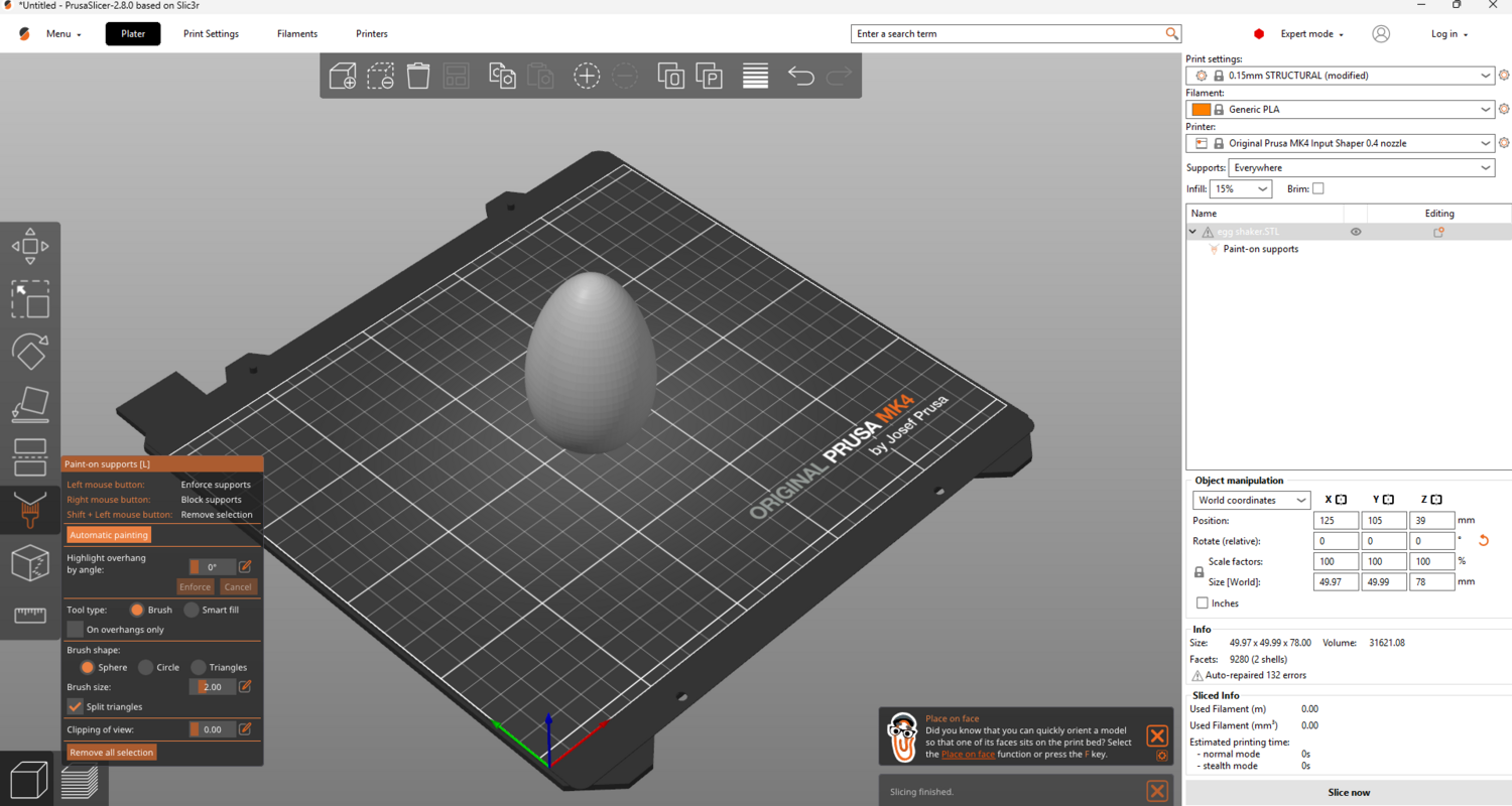
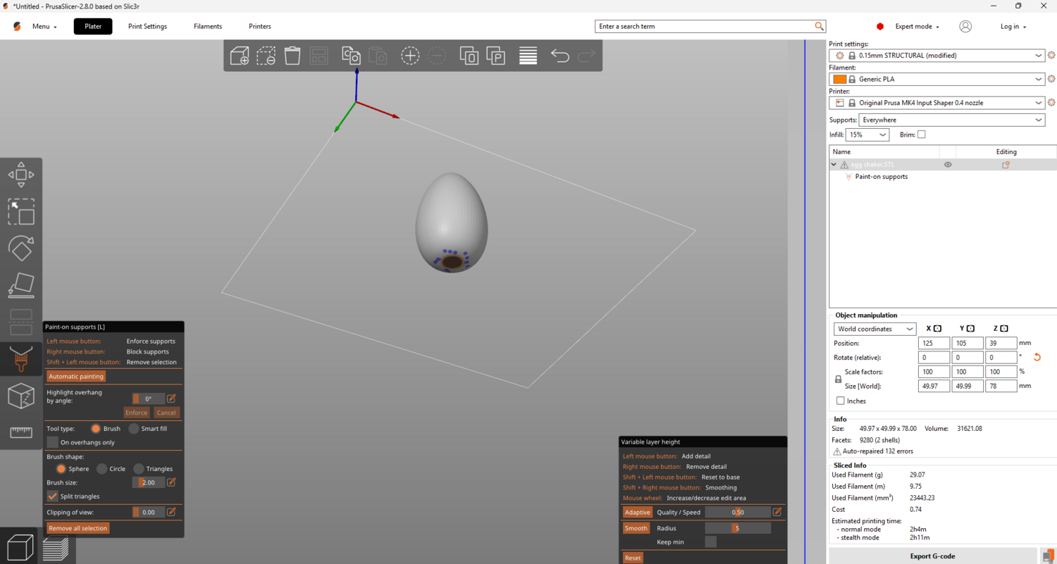
Step 20: Now go back to the Plater. Click the icon with a brush, this is the paint on supports option. You can then click Automatic Painting, however if there is a certain way/place you want your supports you can manually paint it on.
The blue dots represent where the supports will be on your project.
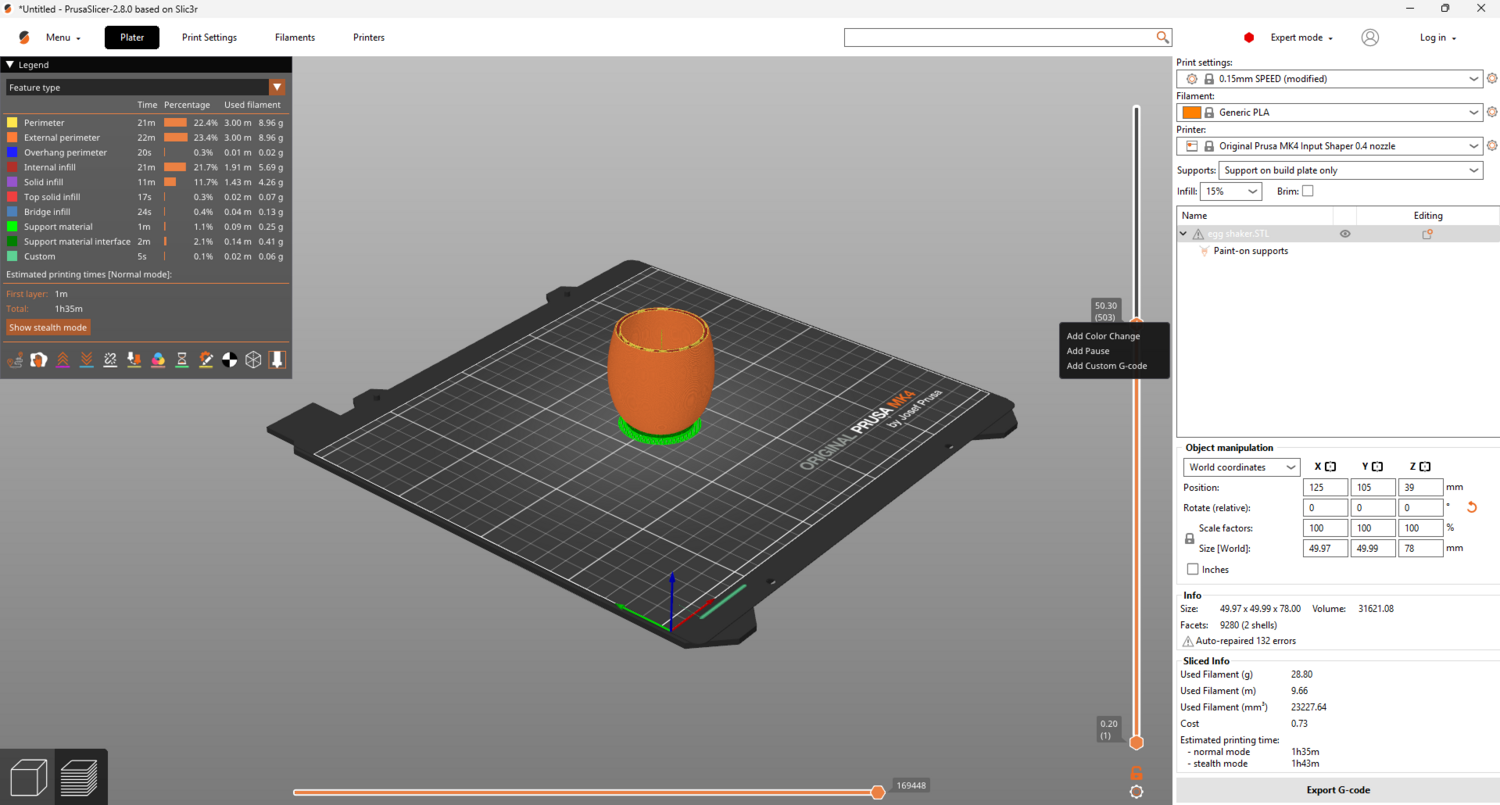
Step 21: In the left column, choose your print settings, typically best to choose from 0.15mm STRUCTURAL or 0.15mm SPEED, filament, typically PLA, printer, check availability and choose between mk4 or mk4s, and supports, depending on part choose everywhere or from build plate only.
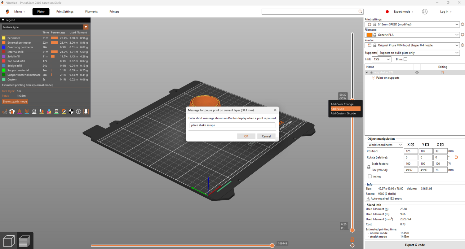
Step 22: For this part, we need the print to pause about half way through so we can fill it with beads. Drag down the slicer on the right to the point in which you want the print to pause, then right click the orange plus icon and click add pause, you can them name the command.
Step 23: Click Slice now in the bottom right corner. After PrusaSlicer finishes rendering, use the vertical slide bar on the right to step through each layer. You can zoom in/out with the scroll wheel and pan by clicking and holding the scroll wheel.
Printing
Step 24: If everything looks good, click Export G-code in the bottom right corner and save the G-code on an SD card. You are now ready to take the SD card to one of the Prusa 3D printers and begin your print (make sure the MK3/MK3S on the printer matches what you selected in PrusaSlicer). Log your print and use the dry erase markers to record your contact info and print duration. Clean the build plate with a few drops of alcohol before you start your print.
Step 25: It's a good idea to monitor the print's first layer closely. Ensure the first layer is adhering well to the build plate. The transition between the first and second layer occasionally requires attention as well. The print fan often turns on after the first layer is completed. If the fan speed of the print fan is too high, the nozzle/hotend will not be able to maintain the correct temperature for extruding. If the nozzle temperature stays more than 10 degrees below its set value for too long, a thermal runaway error will occur and the part will fail. The fan speed can be adjusted using the Tune menu on the printer as the print is going.
Step 26: When the print pauses, add in your material of choice, I uses craft beads. You are welcome to experiment with different shaker materials for various sounds and loudness. The internal volume of the egg is approximately 71ml, so 15ml of shaker material is a good place to start since it fills about 21% of the internal space. Ensure that the height of the shaker material inside the egg will not interfere with the movement of the nozzle/hotend. Resume the print and check on it periodically as it finishes.
Finishing
Step 27: Once the print finishes, remove the entire build plate from the printer (it is magnetically held in place). Gently flex the build plate in various directions to loosen the print. Use your hands to pull the print and support structure off. Only use the scraper as a last resort for removing the print. Scrapers damage the build plate and shorten their lifespan. Reset the space for the next person who will use the printer after you.
Step 28: Remove all of the support structures from the egg and recycle them or throw them away. Use some sandpaper, hand files, and/or the Belt/Disc Sander to smooth out the places where the supports made contact with the egg.
Step 29: You should now have a functional egg shaker! Go make some music.
