Difference between revisions of "Egg Shaker"
| Line 74: | Line 74: | ||
<br> | <br> | ||
<br> | <br> | ||
| − | <strong>Step | + | <strong>Step 14:</strong> Use the Trim Entities tool to get rid of two parts of the diagonal line and part of the offset curve to create the shape shown in the screenshot below. The Trim Entities tool functions by clicking and dragging a line across the parts that you want to disappear. The resultant shape should turn grey to indicate that it is a closed area. |
| + | |||
| + | [[File:Egg 14.png|1500px|none]] | ||
| + | <br> | ||
| + | <br> | ||
| + | <strong>Step 15:</strong> | ||
Revision as of 18:27, 12 April 2021
In this TV, we will take you through the steps of designing an egg shaker in SolidWorks and then 3D printing it using the Prusa 3D Printer.
Procedure
Open SolidWorks 2020, and select a new part. Don't forget to save your file frequently as you go.
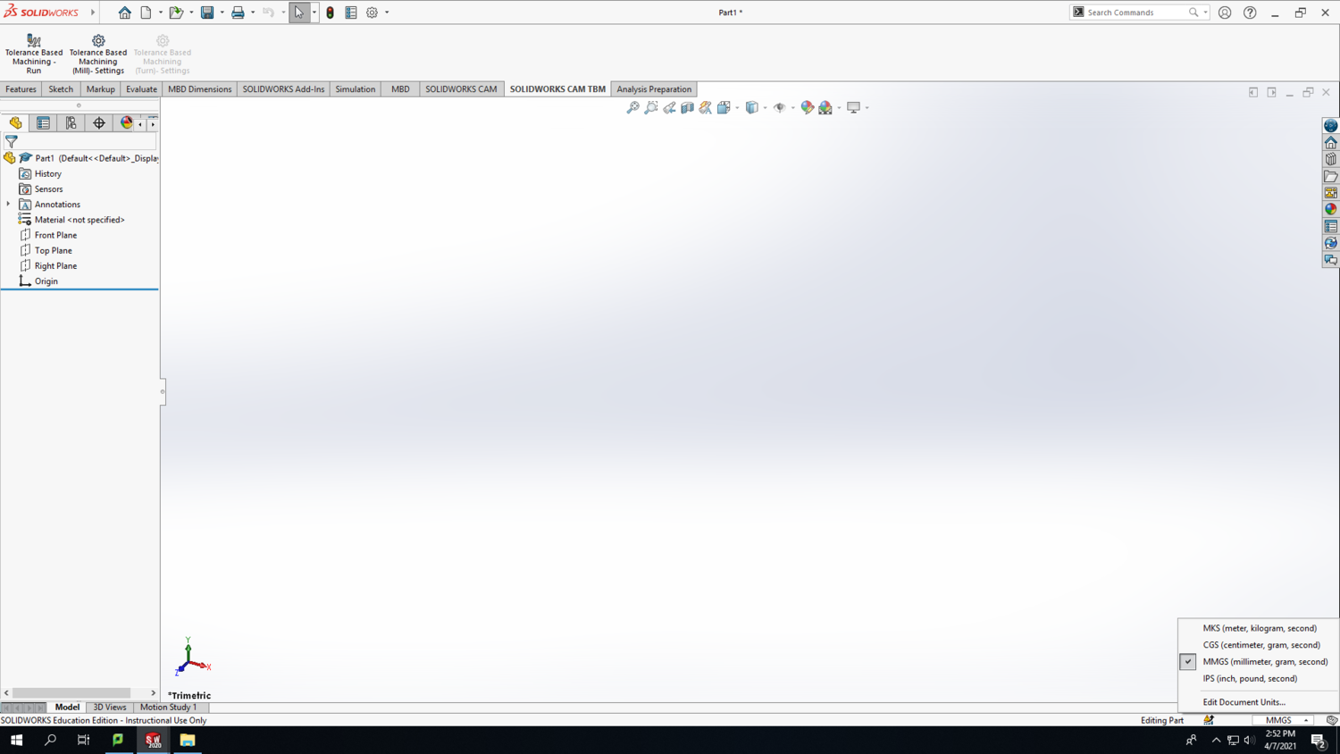
Step 1: In the bottom-right corner of your Solidworks window, change the units to MMGS (millimeter, gram, second).
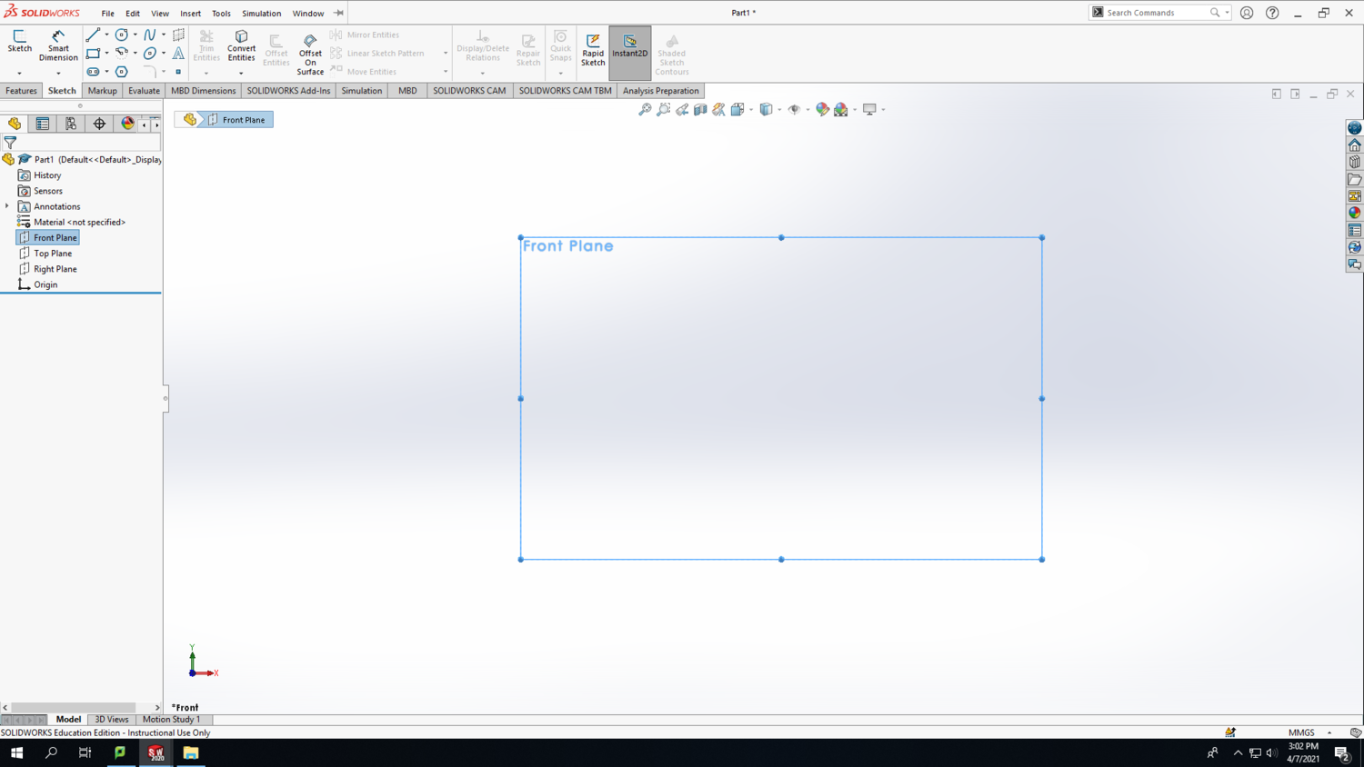
Step 2: Select the Front Plane in the design tree (the left column on your screen) to begin your sketch. Click on the Sketch tab above and click Sketch.
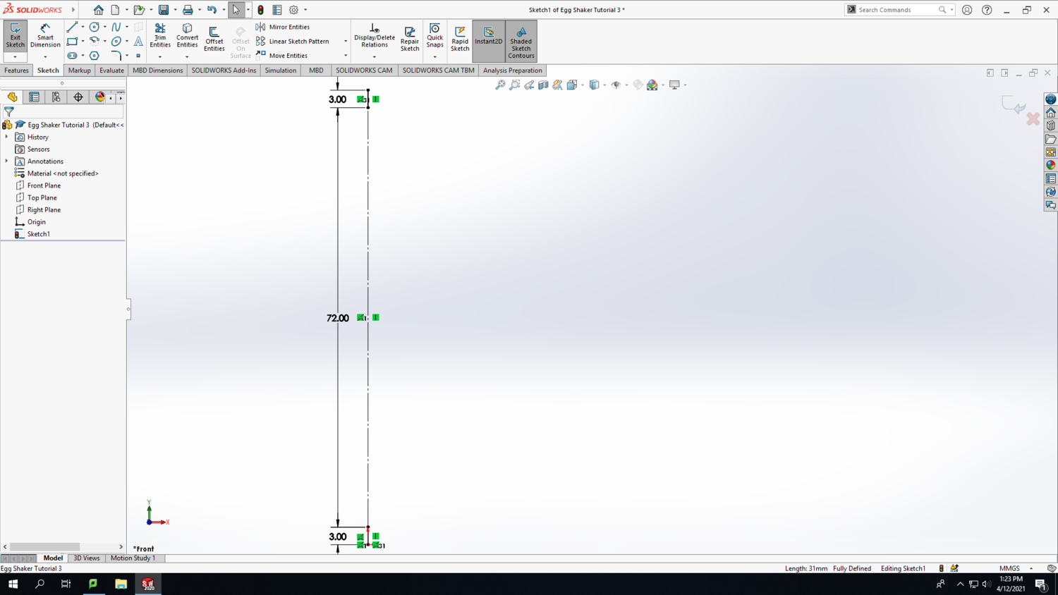
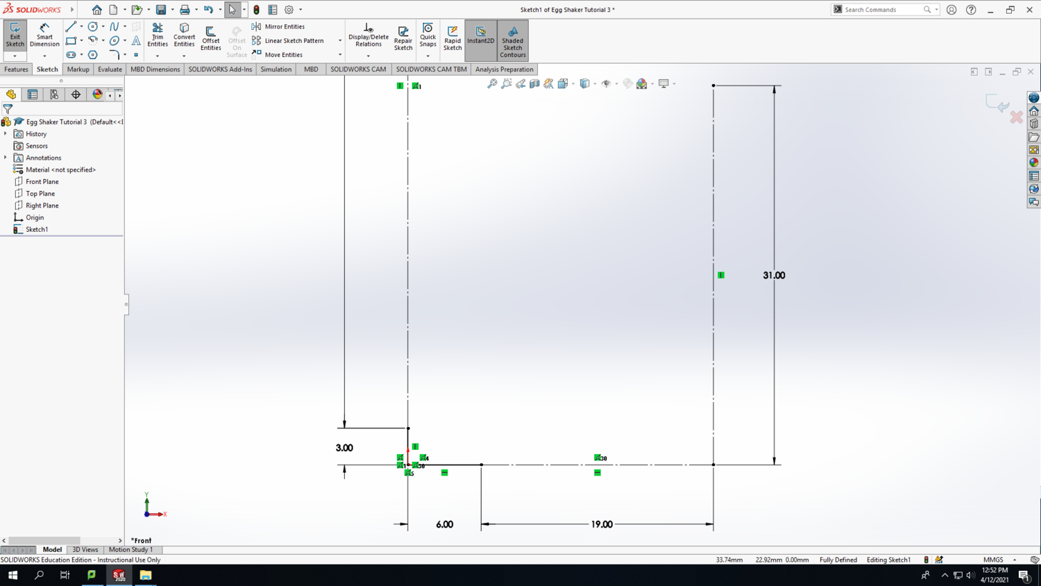
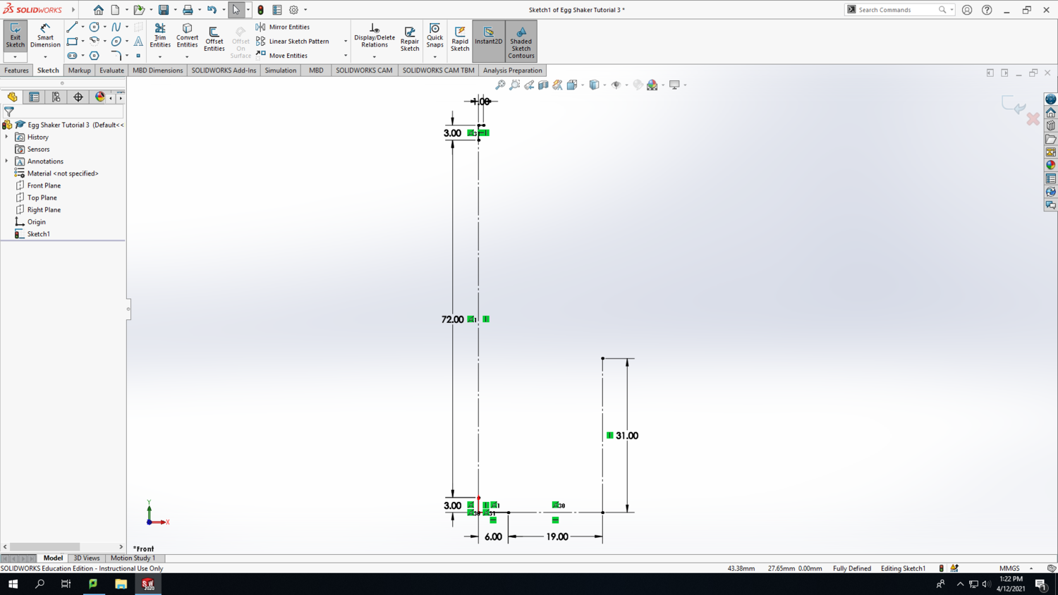
Step 3: Make a vertical line starting from the origin. Then use the smart dimension tool to make it 3mm tall. Follow the same process to draw 2 more lines stacked on top of one another, and make them the lengths shown in the screenshot below. Make the inner line a construction line by clicking on it (after exiting the Smart Dimension tool) and hovering over the icons until you find the "Construction Geometry" icon. After clicking it, the line will become dashed.
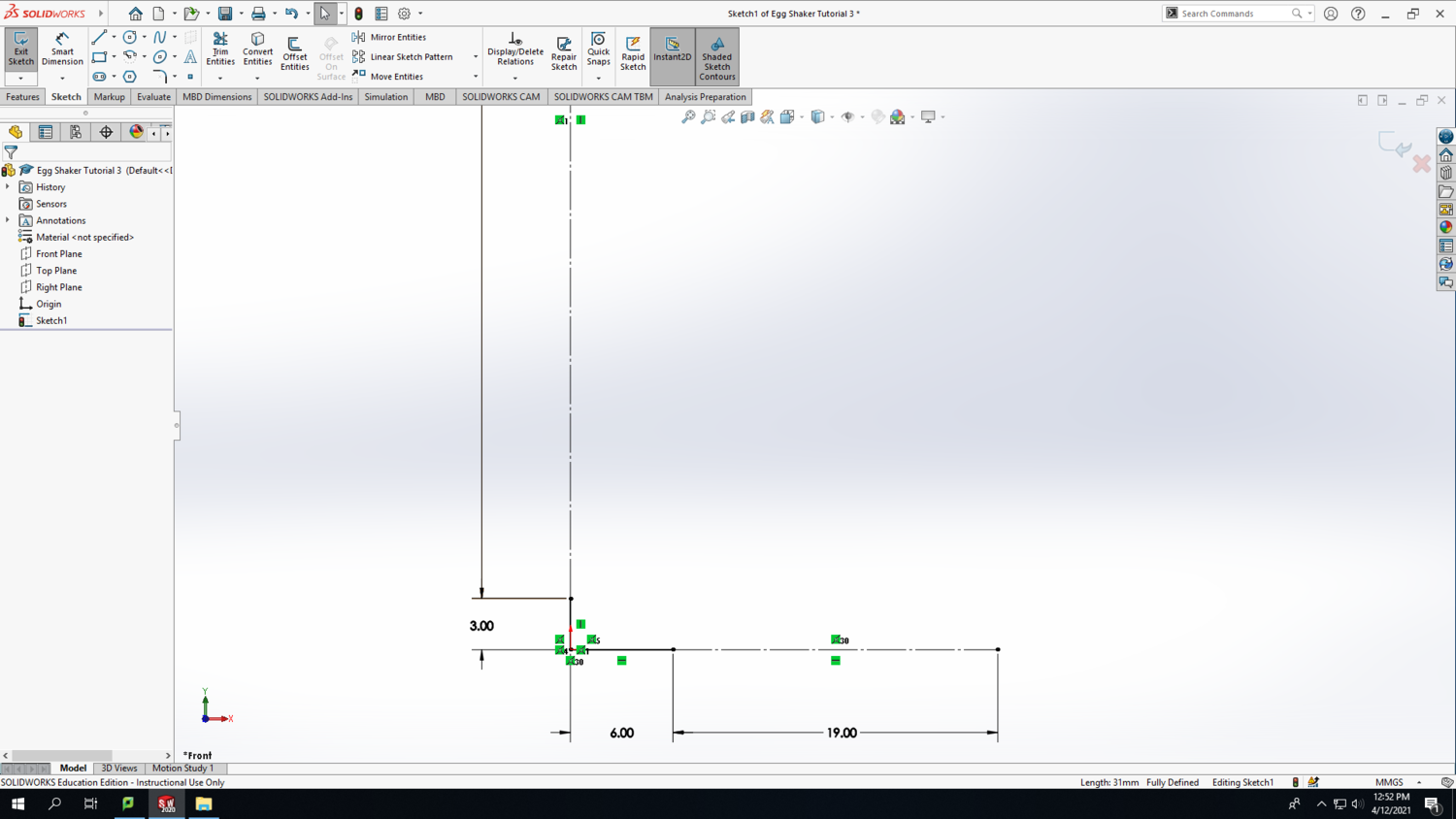
Step 4: Make a horizontal line starting from the origin. Then use the smart dimension tool to make it 6mm long. Draw another horizontal line next to it with the length shown in the screenshot below. Make the second line a construction line by clicking on it (after exiting the Smart Dimension tool) and hovering over the icons until you find the "Construction Geometry" icon. After clicking it, the line will become dashed.
Step 5: From the right end point of the horizontal construction line, draw a vertical construction line with the length shown in the screenshot below.
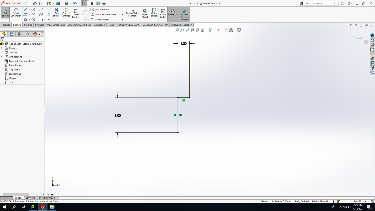
Step 6: At the top of your sketch, draw a 1mm horizontal line at the location shown in the screenshot below.
Step 7: At this point, you should have a total of 4 solid lines and 4 construction lines that look like the screenshot below.
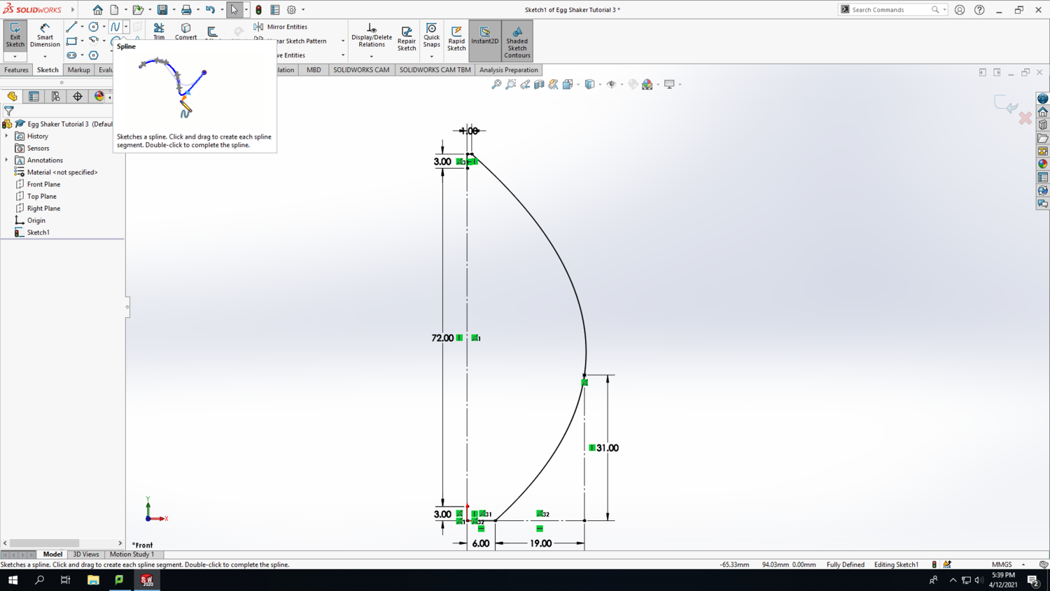
Step 8: Use the spline feature to connect 3 points on your sketch and create a side profile of your egg. Order does matter, so click sequentially from top to bottom or bottom to top on each of the 3 points. Press Esc to finish the spline. You'll notice that it doesn't really look like the side profile of an egg yet, but we'll fix that shortly.
Step 9: Now, you are encouraged to use your creativity to tweak the side profile of the egg to your own taste. I'll give a couple suggestions for how to tweak the spline for best results, but you are welcome to change the lengths of any of the construction lines to get different results. When you have the spline selected, you will see "adjustment arrows with diamonds" that are tangent to the spline. They can be manipulated to change the shape of the curve. Click and drag the diamond to change the angle; click and drag the arrowhead to change the length; click and drag the point at the tip of the arrowhead to simultaneously change both the angle and the length. You always can press ctrl-Z to undo a change and revert back to the spline's previous shape.
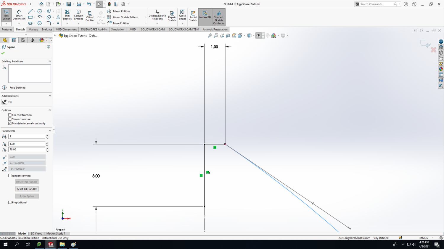
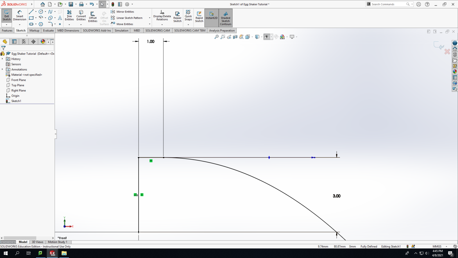
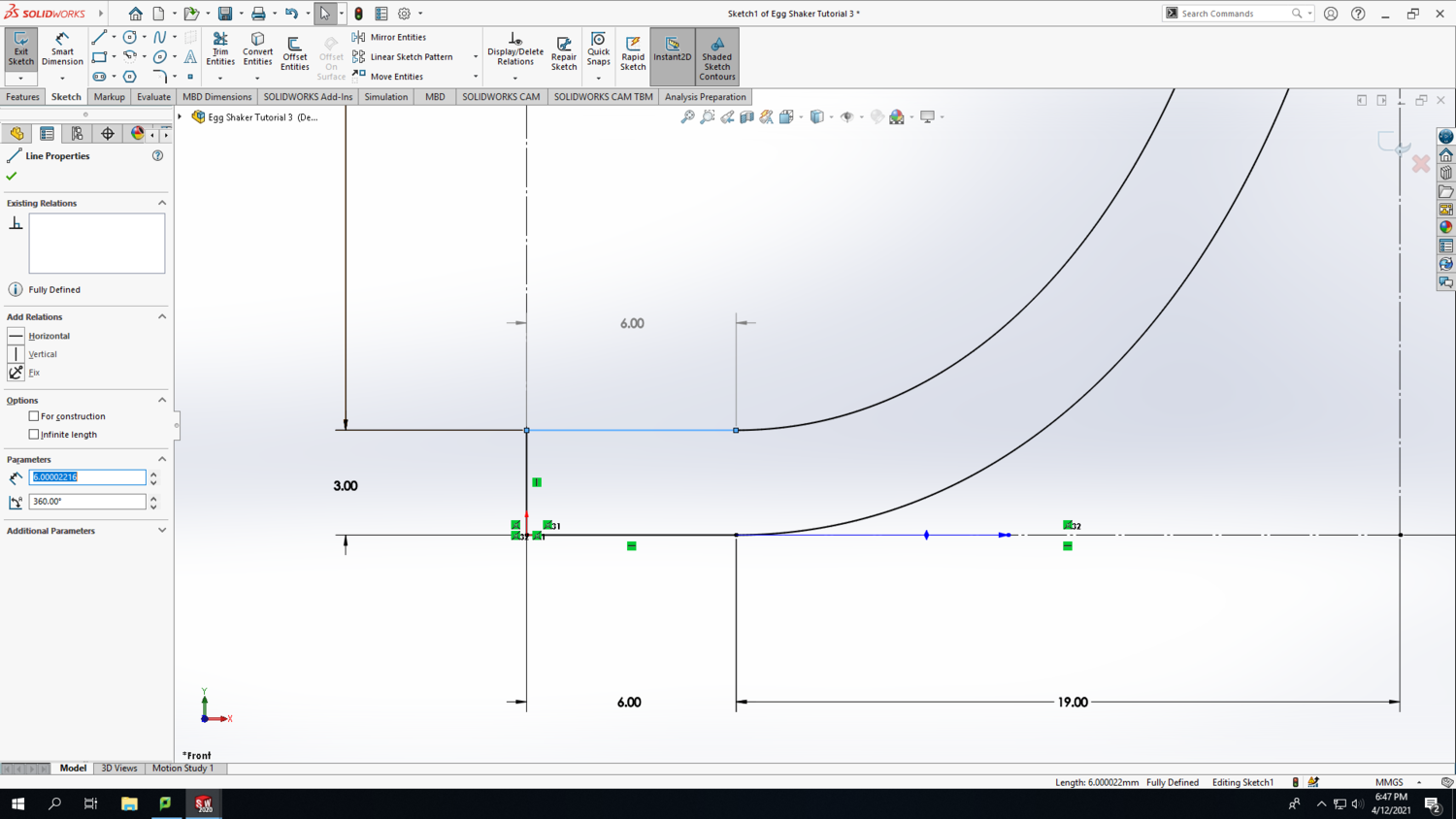
If you zoom into the top of the egg, you'll notice that the spline connects to the 1mm horizontal line at an angle (see the first screenshot). We would like the spline to be approximately horizontal at the point of connection with the 1mm line. This will give the appearance of a nice continuous curve, but it doesn't need to be exact. To do that, pull the Smart Dimension of the 3mm line over to the right side to give yourself a reference. Then move the adjustment arrow thing from the spine parallel with the Smart Dimension reference line (see the second screenshot).
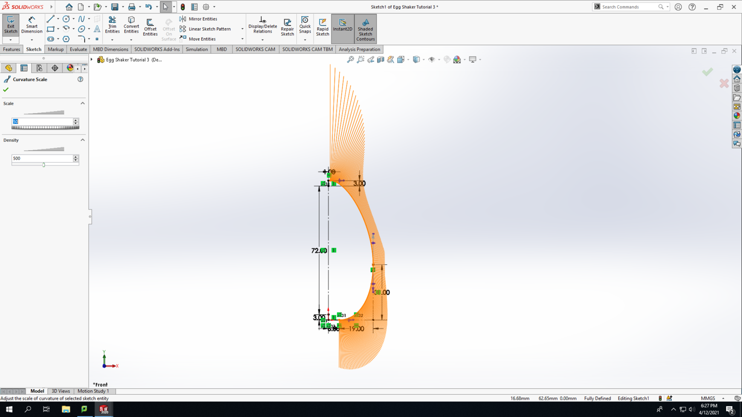
Step 10: Zoom into the bottom of the egg and perform the same operation on the intersection between the spline and the 6mm line. Again, the goal is to make the spline approximately horizontal where it connects with the 6mm line to maintain the continuity of the curve. As you manipulate the spline, you might like to click on the Show Curvature checkbox in the left column to see a visual representation of the intensity of the spline's curve at each point. Change the curvature scale and density to taste.
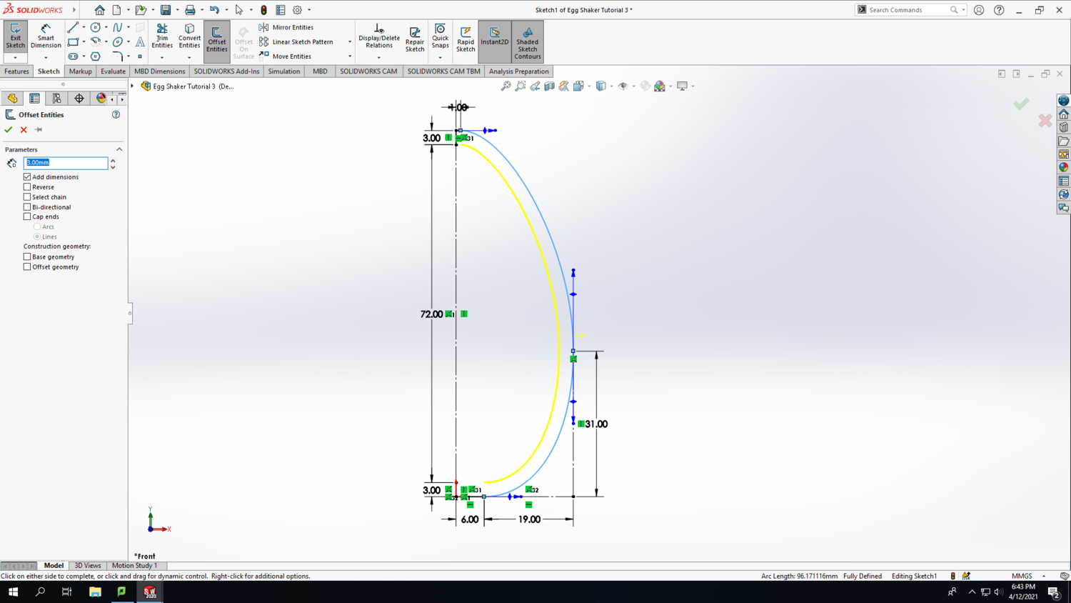
Step 11: One you are happy with the shape of your spline, you can deselect Show Curvature. Select the spline and click on Offset Entities. Set the distance to 3mm; this is defining the wall thickness of your egg. Make sure the new offset curve is on the inside of your spline. Toggle the Reverse checkbox to switch the offset curve between inside and outside.
Step 12: Connect the offset curve to the vertical 3mm line at the bottom of the egg with a horizontal line.
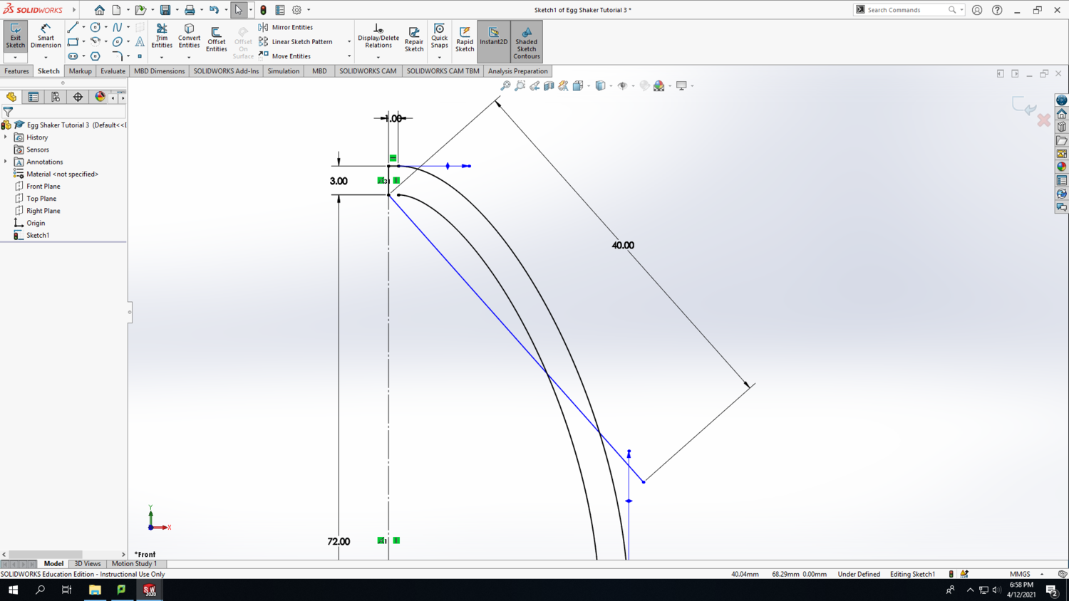
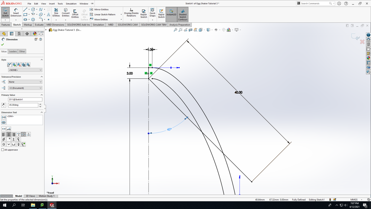
Step 13: Arbitrarily, draw a diagonal line from the point shown in the first screenshot below and set the length to 40mm long using the Smart Dimension tool. Notice that when you click elsewhere to deselect the line you just drew, it doesn't turn black like the rest of the lines in your sketch. This is because the line is "Under Defined," which is also indicated at the bottom of the SolidWorks screen. To fully define this line, click on the diagonal line and the vertical 72mm construction line using the Smart Dimension tool to set the angle to 45 degrees. The result should look similar to the second screenshot below.
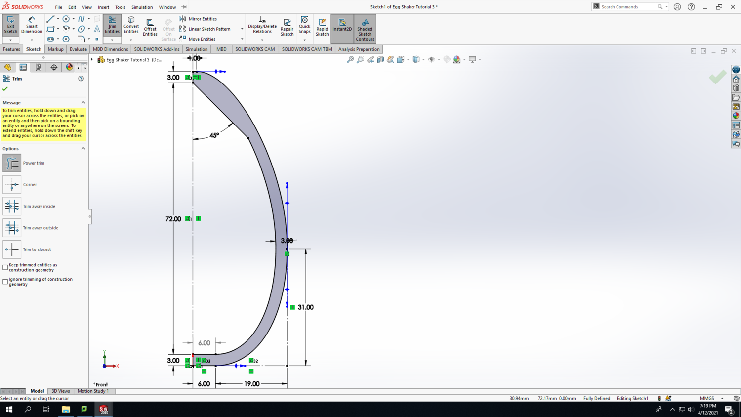
Step 14: Use the Trim Entities tool to get rid of two parts of the diagonal line and part of the offset curve to create the shape shown in the screenshot below. The Trim Entities tool functions by clicking and dragging a line across the parts that you want to disappear. The resultant shape should turn grey to indicate that it is a closed area.
Step 15:
