Difference between revisions of "Speedy 400"
| Line 124: | Line 124: | ||
====Specific Maintenance Tasks==== | ====Specific Maintenance Tasks==== | ||
{| class="wikitable" | {| class="wikitable" | ||
| + | ! | ||
!Maintenance Procedure | !Maintenance Procedure | ||
!Frequency | !Frequency | ||
!Done By | !Done By | ||
| + | !Last Done | ||
|- | |- | ||
| − | | | + | |1 |
| − | | | + | |General cleaning |
| − | | | + | |As needed after a cut |
| + | |Student | ||
| + | |N/A | ||
| + | |- | ||
| + | |2 | ||
| + | |Clean the Mirror | ||
| + | |As needed | ||
| + | |Volunteer | ||
| + | | | ||
| + | |- | ||
| + | |3 | ||
| + | |Clean the Lens | ||
| + | |As needed | ||
| + | |Volunteer | ||
| + | | | ||
| + | |- | ||
| + | |4 | ||
| + | |Change Filters | ||
| + | |When filter usage reaches 100% | ||
| + | |Ace | ||
| + | | | ||
|} | |} | ||
| − | + | # The honeycomb should be removed and the metal bed itself should be should be swept/cleaned more or less daily. Cleaners are available to help in this process. Green is general cleaning use this for the bed and metal surfaces. Blue is glass cleaner, use this for the plexiglass surfaces. The front door of the Speedy 300 may be removed using the spring loaded pin on the right to remove cut pieces stuck in the door. The air vents at the rear of the machine should be kept clean of debris. Clean in a manner similar to the bed. | |
| − | + | # The lense, mirror, and cone should be inspected daily or more often as needed, especially after wood or other “dusty”/”smokey” materials are cut. The lense will need cleaning when particles are visible on the surface (hold up to light if need be). The lense may be removed using the threaded nut below the lense (see photo). The lense should be cleaned with the lense paper and cleaner available in the kit (lasercutter drawer) on both sides. Put some cleaner on the lense and gently rub the paper over the surface of the lense. The cone itself threads into the assembly below the lense nut. The cone may be cleaned with a paper towel and water or another cleaning agent. The mirror should be inspected and cleaned in the same manner as the lense. | |
| − | + | # See above. | |
| − | + | # The air filter to the right of the Speedy 300 will occasionally need maintenance. The most common issue is a full pre-filter. This will be indicated on the filter itself by poor airflow/suction. When replacing this, use a face mask and gloves (close the lab when doing this). Open the top of the air filter with the large 10mm hex wrench in the kit. Remove the prefilter and place it in a bag for disposal. Insert a new prefilter and close the lid. Pre-filters are used to increase the lifespan of other, harder to replace and more expensive filters in the system. Less often, other filters will need replacing. These include the larger box filter, additional pre-filter-type mat filters, and activated carbon. This should not need to happen as often. Follow the above procedure for pre-filter and the [https://www.youtube.com/watch?v=yJkCgAVbAEU&feature=youtu.be video] to replace the full filter setup. Be careful not to spill activate carbon if doing a full replacement, it is difficult to clean up. | |
== Documentation == | == Documentation == | ||
Revision as of 10:51, 11 June 2020
Make: Trotec
Model: Speedy 400
Ace: Jack Sides jsides22@georgefox.edu
Location: Prototype Lab
Description
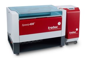
The Trotec Speedy 400 laser engraver is used to engrave and cut materials based on specified images and shapes. The working area of the laser is 24" x 29". This is useful for making enclosures out of acrylic, engraving designs into many materials, creating trophies, and cutting any two dimensional shape out of a variety of materials. It also has a rotary attachment which enables cylindrical objects such as drinking glasses and hydro flasks to be engraved with detailed designs.
Here is an example of this piece of equipment being used.
Insert video media here.
Documentation
Terminology
- Inkscape - The program you will be using to design is Inkscape. It allows you to type in words, edit logos, make your own logos and such to engrave or cut out of your material.
- Job Control - The program that interacts with the laser cutter to perform a cut. Job Control lets you set up/create Material Profiles, change between the HoneyComb Table and the Rotary tool (mostly used for Hydroflasks), and choose a location to cut on your material.
- Focusing tool - Used to focus the laser cutter.
- Stroke - This is the type of line that should be used when cutting.
- Repeat Cut Line - Can be used in JobControl to reproduce the same cut line that was just cut.
- Outline Job - Can be used in JobControl to trace the job that is going to be cut to show where job extends.
- Bitmap - Representation of an image as bits of information (pixels); used to allow logos/stencils to be changed into colors.
- Vector - Representation of an image as shapes, rather than bits; used to allow logos/stencils to be modified as objects.
- Trace Bitmap - Can be used on a bitmap to to turn it into a vector.
- Honeycomb Table - This is the honeycomb shaped metal tray that holds flat material during a cut. It is used for most cut jobs.
- Rotary Tool - When engraving water bottles or glasses, this accessory is used to hold the object in place as well as rotate it while performing a cut.
User Manual
Training
Overview
Performing a cut or engrave with the laser will always begin with Inkscape by opening/importing an image, pdf, DXF, or similar file. If you do not have a file yet then it can also be used to create geometries. Once a file has been brought into Inkscape, it must be adjusted so that job control can distinguish between what should be cut out of the material and what should be engraved. A cut is indicated by a hairline red stroke (in the RGB color scheme) and an engrave is indicated by the color black. After the graphic is prepared, it is transferred to job control using [File] > [Print] and making sure trotec is selected as the device. It will then pop up in the job list on the right hand side of JobControl. At this point the laser cutter should be set up by turning it on, placing the material on the honeycomb table, and then raising the table to focus the laser. The final steps are then to click the USB icon in job control to connect to the laser cutter, drag the job onto the to scale honeycomb table, set the correct material properties, and then click the play button to perform the cut/engrave. When performing an engrave on a cylindrical object, the set up process in Inkscape is the same but there are a few differences in job control and laser cutter itself. Primarily, the honeycomb table must be exchanged for the rotary tool, which must be done while the laser cutter is OFF. The laser cutter should automatically recognize that the rotary is attached. The only change in job control is that the accessory should be changed in the settings from the honeycomb table to the rotary tool.
Demonstration
First, import a George Fox logo into Inkscape and set it up so that the logo is an engrave with a cut circle surrounding it. Once this is done, print the job to job control and run the job on a piece of scrap material.
General Procedure
- Setting up a Job
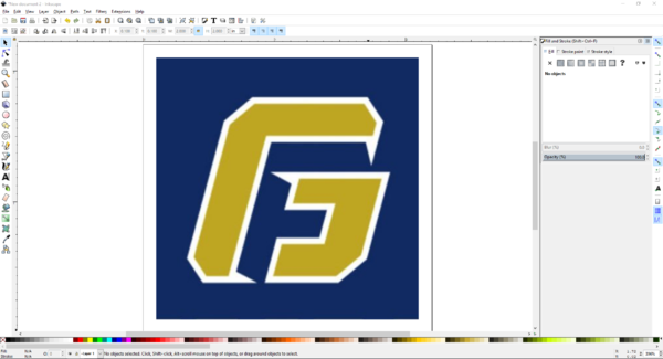
- First off, to get your design, just copy an image and paste it into Inkscape or find a pdf version of the file and open it. If you are cutting a part from a Solidworks file it must be saved as a dxf before importing to Inkscape.
- To open a dxf file go to [File] > [Import]. If a dxf file is being used feel free to skip to step 7.
- Measure the size of your material, and set the page in Inkscape to those dimensions. You can alter the dimensions of the page you are putting the image on by selecting [File] > [Document Properties], and even the width (W) and height (H) image itself in the top. If you want to keep the image dimensions consistent, but just scale it down, click the lock button between these dimensions. If you want to make your own design using text, squares, circles, etc, you can find everything you need in the column on the far left of the client.
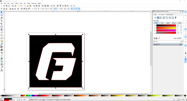
- Once you have your design, we need to alter the colors a little bit so the Laser Cutter can understand what you want it to do. It goes like this: a red stroke will cut, and anything that is black will engrave. A stroke is merely an option that outlines the object you select.
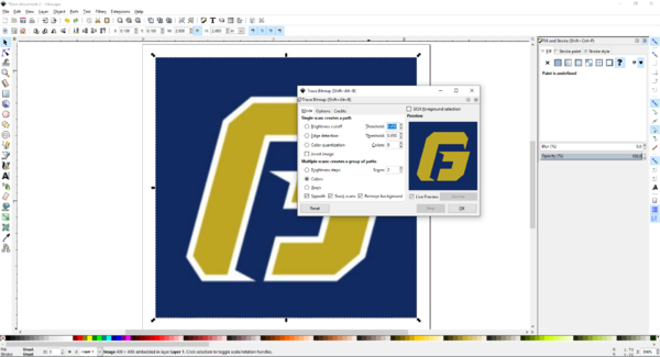
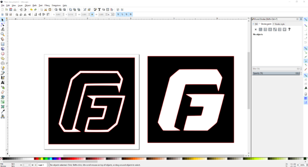
- In order to do this, we need to split up the image into different pieces. This is called vectoring, where it will divide the image into different pieces based on shapes and color. Just select the logo, right click, and select Trace Bitmap. You will be given options shown in the picture below. For this application,we want to separate the colors from each other, so we select the Colors option. The number of scans you have selected will define how closely the vector output will replicate the actual photo (the bitmap) or how many colors you want the vector to tape. Since this is a simple logo and we have 3 colors/shades to take, 3 scans will be enough. If the detail is not good enough, try the other options and have some fun. Once this process is finished, the vector will appear directly on top of the original image, so make sure to drag it off and separate the two before beginning.
- Since there are a few separate parts to this vector, it is possible to break apart these and alter the image however you want. Select the image, right click and go to Ungroup. Now you can mess with each individual part! You can take either of these designs and delete them, essentially they will cut out and engrave the same design. Let's go with the one on the right.
- Now we can manipulate the colors. Select the object and go to [Object] > [Fill and Stroke] (usually it will already be open on the right sidebar). You will see Fill, Stroke Paint, and Stroke Style on the top right. Fill changes the color of a piece, Stroke Paint changes the color of a stroke, and Stroke Style changes the thickness and style of a stroke. You will see values for R, G, and B, where all colors can be made using these. When each color has a 0 next to it, it will be fully black. When the red has a 255 next to it and the others have 0, it will be fully red. Make sure you check these bit values before continuing, since the machine is set to cutting material ONLY when it sees 255, 0, 0, and it will engrave material ONLY when it sees 0, 0, 0. Everything else, make it white, which is 255, 255, 255. Be sure to make each a Flat Color so that the color is constant throughout the entire object.
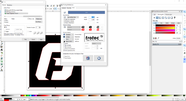
- Once you have finished your design, it’s time to send it to the Laser Cutter! Hit print, make sure it is sending to Trotec Engraver but do not click [OK] yet.
- Select [Preferences] to open the engraver properties. You will want to make sure the [Minimize to Job size] option is NOT selected and that the [Height] - [Width] values match the page size selected in Inkscape. DO NOT have [Enhanced Geometries} selected because it causes the curved parts of your design to be unrecognized once it is uploaded to the Job Control.
- Then you can save these settings by selecting the button that shows the JC logo near the bottom of the Printing Preferences.
- Select Print to send the design to Job Control.
- Setting up the Laser Cutter
- Turn on the machine using the power switch located on the back of the machine in the left corner. The machine will go through a startup procedure where the cutting bed lowers and the laser travels to its home position. Note that the lid must be closed for the startup procedure to begin and there will be some beeping coming from the machine which is normal.
- Place your material onto the honeycomb table, preferably in the upper left corner.
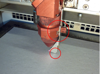
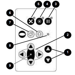
- Now it’s time to focus the laser onto your material. Begin by moving the laser head over the middle of your material; then place the focusing tool on the laser head and slowly raise the table until the the focusing tool falls off. Raise the bed extra slow when reaching the focusing tool so the bed can be stopped the moment the tool falls off. Reference the images below for proper focusing tool placement and laser head controls.
- Remove the focusing tool and return it to its home.
- Press the USB icon found in the bottom right corner of job control to connect to the laser cutter. The laser should beep a few times and then a the background of job control will change to a honeycomb pattern to represent the actual honeycomb table. Also, the USB icon will change to a play icon.
- Cutting with Job Control
- After you send your design to Job Control it will let you name your design and it will store it in a window on the right. If you do not see your design, be sure to select [See All] at the bottom of that window. This lets you see files ALL dpi types, rather than just a specific dpi type.
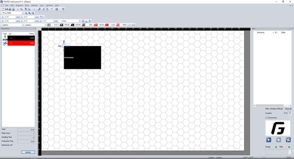
- Double click/drag your design into the middle area and lock the top left corner of the design into the bottom right of the cursor.
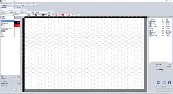
- Then select your material at the top left.You can check the print preview by double clicking the box showing your preview in the bottom right.
- If the cursor is not already visible, be sure that the laser cutter is connected to Job Control via the USB symbol in the bottom right. You can click the Update in the bottom left to see the duration of the job, and now you are ready to click the Play button in the bottom right. For bigger jobs, the Laser Cutter will take a little bit of time to read the design. If it does not start immediately, don’t be scared. Just be supportive and it will begin shortly. If it does not start at all, ask for help from a worker.
- Once the job starts, stay with it. Be sure it is actually engraving/cutting the material. If it is not doing what it should be, stop it by lifting the lid and consult the supervisor for assistance.
- After the job is completed reset the space by cleaning out any scrap materials from the bed and deleting the job from job control and Inkscape.
- Cutting with the Rotary Tool
- The Rotary Tool lets you cut and engrave cylindrical objects, the most popular of these being Hydroflasks. This part applies after you have already sent the file from CoreLDRAW to the Laser Cutter.
- Turn OFF the machine, remove the honeycomb table, and plug in the rotary tool. The rest of the laser cutter setup is the same as above.
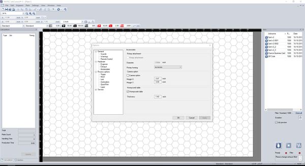
- To start off, go to Settings → Options → Hardware → Accessories. This is where you can switch from the HoneyComb Table to the Rotary Tool and vice versa.
- Enter the diameter of your bottle (using the Calipers in the lab), as it tells the Rotary Tool how fast to turn as it engraves. Do not mess this up, or you will have a stretched/squeezed image.
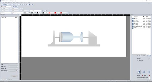
- Once you click OK/apply, the window background will look like the image below.
- Double click/drag the job onto the window. It should automatically flip the image so that it will engrave in the proper orientation even though the bottle is held horizontally.
- Next, pick the material Hydroflask → Black Mug for a Hydroflask, or one of the glass profiles if engraving glass, and now you are ready to engrave your thing!
- When you are finished, RESET THE SPACE! Put the Rotary Tool away and replace it with the HoneyComb Table.
Safety
- Always make sure the material you are using is safe to use. There is an especially high risk when engraving plastics. Fumes from plastics can be toxic. Make sure you find the specific material you are using and check to see if it produces toxic fumes when burned. Never attempt to engrave PVC as it produces chlorine gas (the stuff they used in WWI).
- Once the laser is focused do not touch the button that raises the bed or the laser will crash into the machine which causes damage to the machine.
- Be careful when moving the laser head when using the rotary tool because it has protruding parts that will harm the laser cutter if a crash occurs.
- Keep an eye on active cuts because fires can be started when cutting wood or acrylic with paper covering.
Certification
Troubleshooting
Maintenance
General maintenance
To keep the laser cutter running and cutting smoothly, the mirror and lens should be periodically cleaned. This is on top of the general cleaning that should be done to keep the machine dust and scrap free. There is also filters in the exhaust system that must be changed once the activated carbon has been used up.
Specific Maintenance Tasks
| Maintenance Procedure | Frequency | Done By | Last Done | |
|---|---|---|---|---|
| 1 | General cleaning | As needed after a cut | Student | N/A |
| 2 | Clean the Mirror | As needed | Volunteer | |
| 3 | Clean the Lens | As needed | Volunteer | |
| 4 | Change Filters | When filter usage reaches 100% | Ace |
- The honeycomb should be removed and the metal bed itself should be should be swept/cleaned more or less daily. Cleaners are available to help in this process. Green is general cleaning use this for the bed and metal surfaces. Blue is glass cleaner, use this for the plexiglass surfaces. The front door of the Speedy 300 may be removed using the spring loaded pin on the right to remove cut pieces stuck in the door. The air vents at the rear of the machine should be kept clean of debris. Clean in a manner similar to the bed.
- The lense, mirror, and cone should be inspected daily or more often as needed, especially after wood or other “dusty”/”smokey” materials are cut. The lense will need cleaning when particles are visible on the surface (hold up to light if need be). The lense may be removed using the threaded nut below the lense (see photo). The lense should be cleaned with the lense paper and cleaner available in the kit (lasercutter drawer) on both sides. Put some cleaner on the lense and gently rub the paper over the surface of the lense. The cone itself threads into the assembly below the lense nut. The cone may be cleaned with a paper towel and water or another cleaning agent. The mirror should be inspected and cleaned in the same manner as the lense.
- See above.
- The air filter to the right of the Speedy 300 will occasionally need maintenance. The most common issue is a full pre-filter. This will be indicated on the filter itself by poor airflow/suction. When replacing this, use a face mask and gloves (close the lab when doing this). Open the top of the air filter with the large 10mm hex wrench in the kit. Remove the prefilter and place it in a bag for disposal. Insert a new prefilter and close the lid. Pre-filters are used to increase the lifespan of other, harder to replace and more expensive filters in the system. Less often, other filters will need replacing. These include the larger box filter, additional pre-filter-type mat filters, and activated carbon. This should not need to happen as often. Follow the above procedure for pre-filter and the video to replace the full filter setup. Be careful not to spill activate carbon if doing a full replacement, it is difficult to clean up.
Documentation
Essentially the same as Speedy 300. The Speedy 400 uses the same software and general setup as the Speedy 300, however it has a larger bed and a few backend setting differences.
NOTE: Currently, the Speedy 400 should not be used for acrylic**. There are some issues with settings/airflow that cause acrylic to often catch fire while cutting (which, as you would imagine, is bad)
** If you know what you are doing and are very careful, small (<10 inches) pieces of 1/4" or 1/8" acrylic allow for sufficient airflow to avoid catching fire. Small pieces of 1/2" acrylic can often work as well, as long as you are careful. If the fumes light fire while cutting, pause the print IMMEDIATELY (the same button as start), or, if needed, stop it entirely (although this will abort the cut and you will not be able to continue). Often pausing allows the fire to go out and the acrylic to cool down, so for small cuts you may be able to continue, carefully, after pausing. If you must cut large sheets of acrylic, remove the paper from the area you are cutting, as close to the size of your cut as possible. Although it is not the paper that is burning, removing it seems to reduce the possibility of fire. Try not to remove any more paper than absolutely necessary, as the paper keeps the acrylic clean and protected from scratches when in the stock pile.
