Difference between revisions of "Mood Lamp"
| Line 82: | Line 82: | ||
[[Image:TV_Mood_Lamp_Mitered_Base_With_Hole_DXF_Text.png|500px]] | [[Image:TV_Mood_Lamp_Mitered_Base_With_Hole_DXF_Text.png|500px]] | ||
| + | *Now we want to color code the design for the router. This isn't strictly necessary, as it can be done on the router, but as we are here and it is quick, let's go ahead and do it. Download the [[File:Shaper_Origin_Template.svg|Shaper_Origin_Template.svg]] file and import it into your design. | ||
* This is what will be loaded by thy router.If you have an account on the [https://www.shapertools.com/hub/ Shaper Hub], then load your file there. To get an account, set it up on the router itself. There is presently (7/15/2019) not a way to add an account from a computer. If you do not have or cannot get an account, copy your file to a USB drive. This can be uploaded directly into the device. | * This is what will be loaded by thy router.If you have an account on the [https://www.shapertools.com/hub/ Shaper Hub], then load your file there. To get an account, set it up on the router itself. There is presently (7/15/2019) not a way to add an account from a computer. If you do not have or cannot get an account, copy your file to a USB drive. This can be uploaded directly into the device. | ||
Revision as of 20:26, 15 July 2019
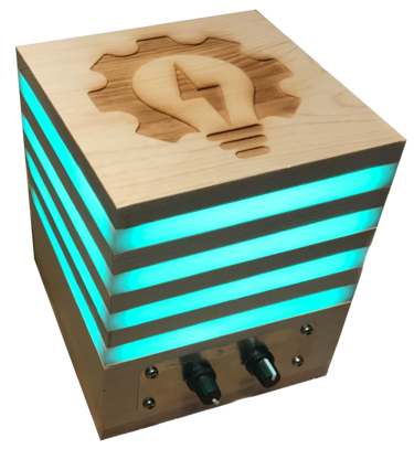
In this TV, we will create a mood lamp. The lamp consists of an internal ...
Bill of Materials
Create the wooden "heels" and "slices"
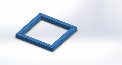
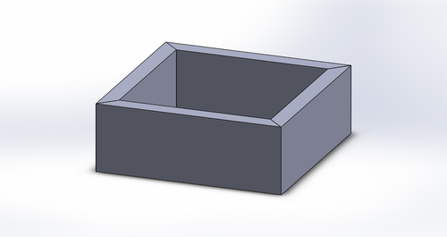
I thought about calling this project the "light loaf" due to the terminology of heels and slices. The heels are the pieces that go on each end of the mood lamp. These are 5.5" square. The slices are made up of 4 mitered 1/2"x5.5" pieces glued together. You will need to create 2 heels and 3 slices. Additionally, you will need to create a base "slice" that will house the controls. This is made up of 4 mitered 2"x5.5" pieces.
Plane the board
You will begin with a 4'x8" board. As everything in the project is based on 1/2" pieces, you will need to initially plane the entire board down to 1/2" thickness
Cut the board
When planning on how to cut your board, you will want to make sure that the grain of the wood runs horizontally along the slices, allowing for maximum strength. One possible way to lay out your wood is given in the picture below. Always remember that you must allow for the kerf of the saw blade. On the table saw, this is generally 1/8".
For this scenario, you might want to do the following:
- Cut a 12" piece off of one end of the board. Rip this to 5.5", then cut 2 5.5" pieces from the remnant.
- Rip a 2" piece off of the length of the board.
- Rip 2 (or 3) 1/2" pieces off of the length of the board.
- Take these pieces that have been ripped, and then cut them into 5.5" strips.
- Miter each of these pieces.
Assemble the slices
- Assemble the 1/2" strips into 3 squares. Glue them up and clamp them in the Angle Strap Clamps.
Introduce yourself to Solidworks
Go to the Solidworks Training page and complete the recommended tutorials. This could take a couple of hours. As a demonstration that you understand the tutorial, design a slice in Solidworks. You can do this by designing the 1/2"x1/2"x5.5" mitered piece, then creating an assembly out of 4 of these. Call these mitered_slice_piece.SLDPRT and mitered_slice.SLDASM.
Assemble the base slice
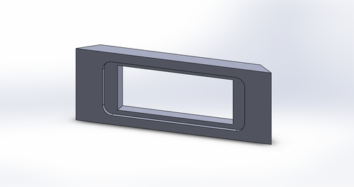
Before assembling the base slice, we will need to cut holes for the controls, as well as an inset so that we can inlay aluminum control plates. Two of the base sides will be unaffected, but two will have the same hole/inset pattern. When the holes and inlays have been cut, the base can be glued and clamped just as the slices were above.
Design the slice in Solidworks
- Make a copy of the slice you designed. Copy both the assembly and the slice (technically, we only need the part file for the router, but we will go ahead and make the assembly so that we have a model of our entire system). Let's call these new files mitered_base_piece.SLDPRT and mitered_base.SLDASM. In the assembly, replace the old part with the new one. In the new part, change the height from .5" to 1/2".
- You will need to make another copy of the mitered_base_piece.SLDPRT. Let's call this mitered_base_piece_with_hole.SLDPRT.
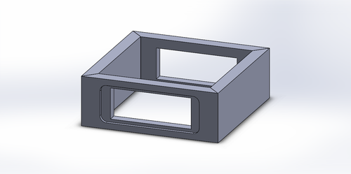
- In this piece, add a rectangle hole in the center, 3.25" wide by 1.25" tall.
- Outside of this, add an inset that is 4" wide by 1.5" tall. This inset should be 1/8" deep. Make sure that the inset is on the outside (the long end) of your mitered part.
- Add a fillet to the inset that has a radius of 1/4".
- Replace a pair of opposite base pieces with the new base piece with hole. This should be your final base.
Prepare the design file for the router
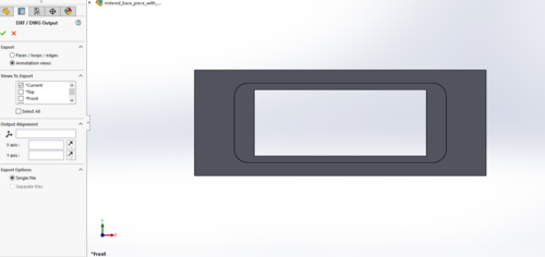
- You will need to export the DXF of your single mitered_base_piece_with_hole.SLDPRT (not the assembly). Open up this file, and set the view so that you are looking at the front of the design (looking through the hole).
- Save this file as a DXF (Save As, then select the DXF format). If a window pops up asking you for a desired options to save the file, select the first one. The DXF window asks you which view to export. If you are already looking at the appropriate view (and you should be), select the "*Current" option and click the check to export the file. This will show you a render of your 2D DXF design. Click save.
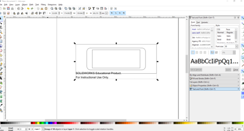
- The router does not use DXF files, but it wants an SVG. So, open Inkscape and import this DXF file. If you are not familiar with Inkscape, this would be a good time to do the training on the Inkscape Training page.
- When you bring the file up in Inkscape, you will see that Solidworks has added some text to the drawing. Delete this text.
- Now we want to color code the design for the router. This isn't strictly necessary, as it can be done on the router, but as we are here and it is quick, let's go ahead and do it. Download the Error creating thumbnail: convert-im6.q16: delegate failed `'rsvg-convert' -o '%o' '%i'' @ error/delegate.c/InvokeDelegate/1928. convert-im6.q16: unable to open file `/tmp/magick-29688LwDHss0akGh5': No such file or directory @ error/constitute.c/ReadImage/599. convert-im6.q16: no images defined `PNG:/tmp/transform_a3bed2352bff.png' @ error/convert.c/ConvertImageCommand/3258.file and import it into your design.
- This is what will be loaded by thy router.If you have an account on the Shaper Hub, then load your file there. To get an account, set it up on the router itself. There is presently (7/15/2019) not a way to add an account from a computer. If you do not have or cannot get an account, copy your file to a USB drive. This can be uploaded directly into the device.
Set up the work piece for the Handheld CNC Router
The Handheld CNC Router expects that it is viewing and routing on a solid surface in one plane. However, we have already cut out our mitered pieces. So, you will need to set up a 1/2" board with tape, and using some double-sided tape or other fastening mechanism, mount the piece to be routed at the bottom of the taped board. Be sure to place the outside of the part upward, so that you route the inset into the proper side. It is also a good idea to stick or mount some 1/2" blocks on either side to give the router a solid base when it is routing your part.
Set up the Handheld CNC Router
Follow the directions given in the Handheld CNC Router Training to
Route the shelf
Route the hole
Assemble the base
Create the Acrylic Slices
Design the acrylic slice in Solidworks
Prepare the Omax Waterjet Software
Cut the slices on the Waterjet
Program the Arduino
Test the Arduino IDE using standard programs
Program the Arduino to read in the A/D values
Verify using the printouts
Program the Arduino
Assemble the electronics
Solder together the screw shield
Solder the transistors onto the shield
Solder the solid-core connecting wires
=== Solder the
== Create the
