Difference between revisions of "Injection Molding Machine"
| (48 intermediate revisions by 5 users not shown) | |||
| Line 1: | Line 1: | ||
{{#set: | {{#set: | ||
|Is equipment=True | |Is equipment=True | ||
| − | |Is located in facility= | + | |Is located in facility=The Vault |
|Is used in domain= | |Is used in domain= | ||
|Has name={{PAGENAME}} | |Has name={{PAGENAME}} | ||
| − | |Has icon=File: | + | |Has make=Pim-shooter |
| + | |Has model=150A | ||
| + | |Has serial number=D00709 | ||
| + | |Has life expectancy= | ||
| + | |Has year of manufacture or purchase= | ||
| + | |Has replacement cost= | ||
| + | |Has icon=File:Injection Molding Machine (1).png | ||
|Has icondesc= | |Has icondesc= | ||
|Has image=File:Model 150a.jpg | |Has image=File:Model 150a.jpg | ||
|Has imagedesc=LNS 150A | |Has imagedesc=LNS 150A | ||
|Has description= | |Has description= | ||
| − | |Has certification= | + | |Has certification=https://georgefox.instructure.com/courses/1280 |
| − | + | |Has ace=Sam Manina;smanina22@georgefox.edu | |
| − | |||
| − | |Has ace= | ||
}} | }} | ||
| − | [[{{#show: {{FULLPAGENAME}}|?Has icon|link=none}}| | + | [[{{#show: {{FULLPAGENAME}}|?Has icon|link=none}}|140px|left|top|{{#show: {{FULLPAGENAME}}|?Has icondesc}}]] |
[[{{#show: {{FULLPAGENAME}}|?Has image|link=none}}|300px|thumb|upright=1.5|{{#show: {{FULLPAGENAME}}|?Has imagedesc}}]] | [[{{#show: {{FULLPAGENAME}}|?Has image|link=none}}|300px|thumb|upright=1.5|{{#show: {{FULLPAGENAME}}|?Has imagedesc}}]] | ||
| Line 20: | Line 24: | ||
Model: {{#show: {{PAGENAME}} |?Has model}} | Model: {{#show: {{PAGENAME}} |?Has model}} | ||
| + | |||
| + | Serial Number: {{#show: {{PAGENAME}} |?Has serial number}} | ||
Ace: {{#show: {{PAGENAME}} |?Has ace.Has name}} ({{#show: {{PAGENAME}} |?Has ace.Has email address}}). | Ace: {{#show: {{PAGENAME}} |?Has ace.Has name}} ({{#show: {{PAGENAME}} |?Has ace.Has email address}}). | ||
Location: {{#show: {{PAGENAME}} |?Is located in facility}} | Location: {{#show: {{PAGENAME}} |?Is located in facility}} | ||
| + | |||
__TOC__ | __TOC__ | ||
| Line 30: | Line 37: | ||
==Description== | ==Description== | ||
| − | The Model 150A PIM- | + | The Model 150A PIM-SHOOTER™ by LNS Technologies is a bench model injection molder designed for production of thermoplastic parts in quantities required for making prototypes and low-volume production (or higher-volume production of small parts). Due to the machine’s small size it is limited to producing small parts, but it is capable of producing these parts efficiently, accurately (as accurate as the mold is), and repeatedly. The plastic shot size is 1.1 cubic inch Max. |
{{#evu:https://www.youtube.com/watch?v=5_UnthpIA0w&feature=youtu.be}} | {{#evu:https://www.youtube.com/watch?v=5_UnthpIA0w&feature=youtu.be}} | ||
| Line 38: | Line 45: | ||
====Terminology==== | ====Terminology==== | ||
| − | Flash - This is when the two halves of a molding tool are not properly sealed, causing molten plastic to leak out of the part cavity | + | '''Flash -''' This is when the two halves of a molding tool are not properly sealed, causing molten plastic to leak out of the part cavity |
| − | Sprue - The main channel guiding the molten plastic from the nozzle of the injection molder into the part cavity. | + | '''Sprue -''' The main channel guiding the molten plastic from the nozzle of the injection molder into the part cavity. |
| − | Runners - Subchannels that branch off from the sprue and into the part cavities. These are used for mold tools that contain multiple part cavities. | + | '''Runners -''' Subchannels that branch off from the sprue and into the part cavities. These are used for mold tools that contain multiple part cavities. |
| − | Gate - The thin section connecting a runner or sprue to the part cavity | + | '''Gate - '''The thin section connecting a runner or sprue to the part cavity |
| + | |||
| + | '''Shot -''' The volume of material needed to fill the mold cavity. | ||
[[File:...injectionMolderTerms.png|none|thumb|469x469px]] | [[File:...injectionMolderTerms.png|none|thumb|469x469px]] | ||
| − | User Manual | + | |
| + | [[Media:Manual_InjectionMolder.pdf|Injection Molding Machine User Manual]] | ||
==Training== | ==Training== | ||
| − | ==== | + | ====Operation==== |
The injection molder works by melting plastic pellets within a heated barrel to a specific temperature, and using a ram plunger to force the molten plastic through a nozzle, into a mold cavity. | The injection molder works by melting plastic pellets within a heated barrel to a specific temperature, and using a ram plunger to force the molten plastic through a nozzle, into a mold cavity. | ||
| Line 60: | Line 70: | ||
====General Procedure==== | ====General Procedure==== | ||
# Setup | # Setup | ||
| − | ## | + | ## You will need to setup the molding machine using the following steps and charts. Temperatures for different plastics can be found in the table below. Make sure to wear gloves and safety glasses while using this machine.[[File:...injectionTemperatureChart.png|none|thumb|373x373px]] [[File:Temp_Controller.JPG|600px|thumb|none]] |
| + | ## First we need to adjust the height for the mold being used by following these steps. | ||
| + | ### Set the mold clamps to measure the gap. | ||
| + | ### Loosen the height adjustment bolts on the top holder using a 6mm Allen Wrench. | ||
| + | ### Loosen both tension nuts, and turn the lower tension nut to move the top holder up and down the main post. This will determine the height of the machine. | ||
| + | ### Raise or lower the top holder so that there is a gap between the nozzle and the mold sprue (this allows adding and removing the mold), but of no more than ½”. | ||
| + | ### Tighten height adjustment bolts, and verify that the nozzle aligns well with the mold sprue. | ||
| + | ### Tighten the upper and lower tension nuts. | ||
| + | # Molding | ||
| + | ## Turn on the power switch. | ||
| + | ## Make sure the SV value is correct on the temp controller for the type of material you are using. Adjust the temp controller using the setting buttons if the SV value needs adjusting. | ||
| + | ## Wait for the PV value to reach the SV value. | ||
| + | ## Now add pellets to the feeder. | ||
| + | ## Wait several minutes for the pellets to melt. If you want to preheat the mold now is the time. | ||
| + | ## You should see a small amount of plastic ooze from the nozzle | ||
| + | ## Make sure the mold is clamped tight and the nozzle nipple is aligned with the mold sprue. | ||
| + | ## Scrape away any oozing plastic from the nozzle using a screwdriver or similar tool. This helps keep plastic chunks out of the mold. | ||
| + | ## With a smooth linear motion push down on the handle and fill the mold. | ||
| + | ## Hold pressure on the handle for an extra few seconds. This will help reduce shrinking of the plastic in the mold. | ||
| + | ## Retract the handle all of the way to remove the plunger and give access to load more pellets. | ||
| + | ## You can now remove the mold and separate the halves. | ||
| + | |||
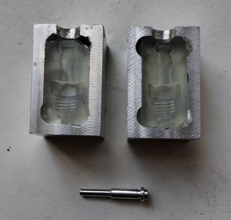
| + | =====Making a Resin Mold for the Injection Molder===== | ||
| + | The Mold: | ||
| + | * Find/make a 3D model of the object you want to mold. | ||
| + | * Follow the instructions in the linked video to turn the object into a 3d model on SolidWorks: | ||
| + | {{#evu:https://www.youtube.com/watch?v=jm9b_8kYKuQ}} | ||
| + | * Save the SolidWorks file as an STL file. | ||
| + | * Then follow the steps in the maker-hub wiki to print this STL file on the Formlabs resin 3D printer. Make sure to use the HIGH TEMP RESIN in the Formlabs and not another type of resin as this kind is the best for injection molding. | ||
| + | ** TIP: Curve the edges of the mold to better fit inside the mold casing | ||
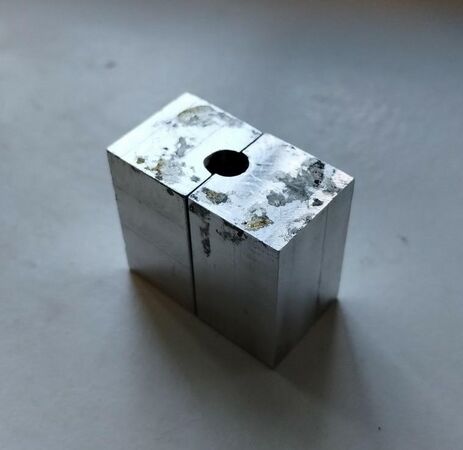
| + | The Aluminum Casing (x2): | ||
| + | * Find a piece of aluminum stock that is larger than one-half of your mold in every dimension. | ||
| + | * Next, cut down the piece using the mill until the aluminum block is somewhere between 1/8”-1/4” larger than the piece of your mold. This will allow a wall of that thickness around your mold. | ||
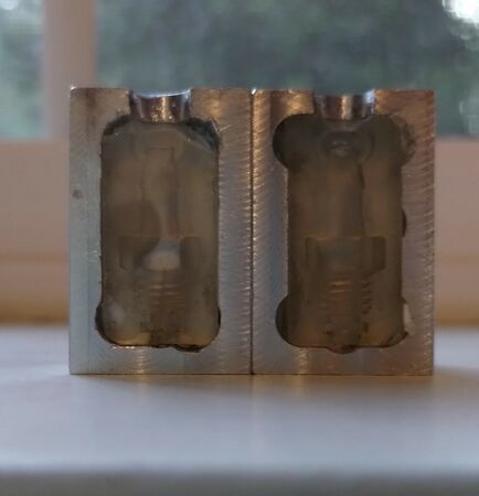
| + | * Then mill out a cavity in the block of aluminum that is around the size of your mold. This cavity will be for press fitting half of the mold into, but it shouldn’t be too tight or else the mold might break. The depth of this cavity should be the same distance as the thickness of the mold piece, so when press fitted the casing and mold faces are flush. | ||
| + | * Then, drill out a hole at the top of the mold for the spout where the plastic will be injected into. | ||
| + | * The printed mold will then be press fitted into the cavity but be careful not to crack the mold when press fitting. | ||
| + | |||
| + | <gallery mode="packed" heights="300px"> | ||
| + | Image:Resin Mold 1.jpg | ||
| + | Image:Resin Mold 2.jpg | ||
| + | Image:Resin Mold 3.jpg | ||
| + | </gallery> | ||
==Safety== | ==Safety== | ||
| − | + | *Parts of the injection molding machine get very hot and could burn you. You need to wear gloves while working with the machine and molds. | |
| + | *Never attempt to use PVC or other materials not approved for use with this machine. PVC will produce toxic fumes when heated. | ||
==Certification== | ==Certification== | ||
| + | Complete <strong>The Vault - {{PAGENAME}} Module</strong> at the link below to gain access to the {{PAGENAME}}. The Maker Hub Canvas course pertains to all facilities and equipment contained in the Maker Hub; simply complete the quizzes for the facilities/equipment you wish to use in the Maker Hub. Please email <span style="color:blue">makerhub@georgefox.edu</span> if you have any questions. | ||
| − | + | [https://georgefox.instructure.com/enroll/GH36RT Maker Hub Canvas Course] | |
==Troubleshooting== | ==Troubleshooting== | ||
| + | It may take some time to learn how much pressure to apply to the handle when filling a mold. If you press too hard you will end up with lots of plastic flash on your finished piece as material will ooze out between the mold halves. If you don't press hard enough you could end up with an air pocket left in the mold. | ||
| + | |||
| + | If you run into an issue with the material not flowing properly make sure that you are heating the material to the correct temperature and allowing enough time for the plastic to melt. | ||
==Maintenance== | ==Maintenance== | ||
====General maintenance==== | ====General maintenance==== | ||
| − | + | The machine should to be cleaned on a regular basis and mechanical parts should be checked for wear as well as loosening of any parts. | |
====Specific Maintenance Tasks==== | ====Specific Maintenance Tasks==== | ||
| Line 82: | Line 138: | ||
!Done By | !Done By | ||
|- | |- | ||
| − | | | + | |Clean up plastic overflow |
| − | | | + | |When used |
| − | | | + | |Student |
|} | |} | ||
Latest revision as of 13:59, 22 August 2024
Make: Pim-shooter
Model: 150A
Serial Number: D00709
Ace: Sam Manina (smanina22@georgefox.edu).
Location: The Vault
Description
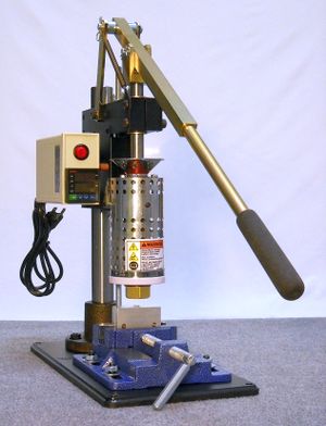
The Model 150A PIM-SHOOTER™ by LNS Technologies is a bench model injection molder designed for production of thermoplastic parts in quantities required for making prototypes and low-volume production (or higher-volume production of small parts). Due to the machine’s small size it is limited to producing small parts, but it is capable of producing these parts efficiently, accurately (as accurate as the mold is), and repeatedly. The plastic shot size is 1.1 cubic inch Max.
Documentation
Terminology
Flash - This is when the two halves of a molding tool are not properly sealed, causing molten plastic to leak out of the part cavity
Sprue - The main channel guiding the molten plastic from the nozzle of the injection molder into the part cavity.
Runners - Subchannels that branch off from the sprue and into the part cavities. These are used for mold tools that contain multiple part cavities.
Gate - The thin section connecting a runner or sprue to the part cavity
Shot - The volume of material needed to fill the mold cavity.
Injection Molding Machine User Manual
Training
Operation
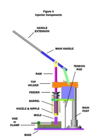
The injection molder works by melting plastic pellets within a heated barrel to a specific temperature, and using a ram plunger to force the molten plastic through a nozzle, into a mold cavity.
Demonstration
For the injection molder demonstration, a pre-existing mold will be provided and the person must successfully injection mold the part. They should demonstrate proper adjustment of height to fit the mold, setting up for injection (filling the hopper, setting the temperature, and aligning the mold under the nozzle), injecting, and removal of the mold and part from the mold.
General Procedure
- Setup
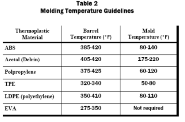
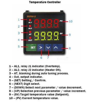
- You will need to setup the molding machine using the following steps and charts. Temperatures for different plastics can be found in the table below. Make sure to wear gloves and safety glasses while using this machine.
- First we need to adjust the height for the mold being used by following these steps.
- Set the mold clamps to measure the gap.
- Loosen the height adjustment bolts on the top holder using a 6mm Allen Wrench.
- Loosen both tension nuts, and turn the lower tension nut to move the top holder up and down the main post. This will determine the height of the machine.
- Raise or lower the top holder so that there is a gap between the nozzle and the mold sprue (this allows adding and removing the mold), but of no more than ½”.
- Tighten height adjustment bolts, and verify that the nozzle aligns well with the mold sprue.
- Tighten the upper and lower tension nuts.
- Molding
- Turn on the power switch.
- Make sure the SV value is correct on the temp controller for the type of material you are using. Adjust the temp controller using the setting buttons if the SV value needs adjusting.
- Wait for the PV value to reach the SV value.
- Now add pellets to the feeder.
- Wait several minutes for the pellets to melt. If you want to preheat the mold now is the time.
- You should see a small amount of plastic ooze from the nozzle
- Make sure the mold is clamped tight and the nozzle nipple is aligned with the mold sprue.
- Scrape away any oozing plastic from the nozzle using a screwdriver or similar tool. This helps keep plastic chunks out of the mold.
- With a smooth linear motion push down on the handle and fill the mold.
- Hold pressure on the handle for an extra few seconds. This will help reduce shrinking of the plastic in the mold.
- Retract the handle all of the way to remove the plunger and give access to load more pellets.
- You can now remove the mold and separate the halves.
Making a Resin Mold for the Injection Molder
The Mold:
- Find/make a 3D model of the object you want to mold.
- Follow the instructions in the linked video to turn the object into a 3d model on SolidWorks:
- Save the SolidWorks file as an STL file.
- Then follow the steps in the maker-hub wiki to print this STL file on the Formlabs resin 3D printer. Make sure to use the HIGH TEMP RESIN in the Formlabs and not another type of resin as this kind is the best for injection molding.
- TIP: Curve the edges of the mold to better fit inside the mold casing
The Aluminum Casing (x2):
- Find a piece of aluminum stock that is larger than one-half of your mold in every dimension.
- Next, cut down the piece using the mill until the aluminum block is somewhere between 1/8”-1/4” larger than the piece of your mold. This will allow a wall of that thickness around your mold.
- Then mill out a cavity in the block of aluminum that is around the size of your mold. This cavity will be for press fitting half of the mold into, but it shouldn’t be too tight or else the mold might break. The depth of this cavity should be the same distance as the thickness of the mold piece, so when press fitted the casing and mold faces are flush.
- Then, drill out a hole at the top of the mold for the spout where the plastic will be injected into.
- The printed mold will then be press fitted into the cavity but be careful not to crack the mold when press fitting.
Safety
- Parts of the injection molding machine get very hot and could burn you. You need to wear gloves while working with the machine and molds.
- Never attempt to use PVC or other materials not approved for use with this machine. PVC will produce toxic fumes when heated.
Certification
Complete The Vault - Injection Molding Machine Module at the link below to gain access to the Injection Molding Machine. The Maker Hub Canvas course pertains to all facilities and equipment contained in the Maker Hub; simply complete the quizzes for the facilities/equipment you wish to use in the Maker Hub. Please email makerhub@georgefox.edu if you have any questions.
Troubleshooting
It may take some time to learn how much pressure to apply to the handle when filling a mold. If you press too hard you will end up with lots of plastic flash on your finished piece as material will ooze out between the mold halves. If you don't press hard enough you could end up with an air pocket left in the mold.
If you run into an issue with the material not flowing properly make sure that you are heating the material to the correct temperature and allowing enough time for the plastic to melt.
Maintenance
General maintenance
The machine should to be cleaned on a regular basis and mechanical parts should be checked for wear as well as loosening of any parts.
Specific Maintenance Tasks
| Maintenance Procedure | Frequency | Done By |
|---|---|---|
| Clean up plastic overflow | When used | Student |

