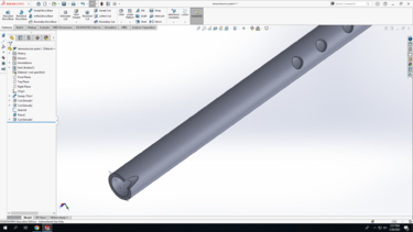
Quena
In this TV, we will be creating a quena.
CAD
IPS
Step 1: Open SolidWorks 2020, and select a new part. Don't forget to save your file frequently as you go. In the bottom-right corner of your Solidworks window, change the units from IPS to MMGS (milimeter, gram, second)
Step 2: Select the Front Plane in the design tree (the left column on your screen) to begin your sketch. Click on the Sketch tab above and click Sketch.
Step 3: Draw out the shape below. Start the lower left corner on the origin (the red arrows), and make sure the lines snap to horizontal and vertical. Using the smart dimension tool, which you can get either on the menu at top, or by holding your right mouse button and dragging up. If done correctly, the entire sketch should be black, indicating that it is fully defined.
Step 4: In the top left corner, click Exit Sketch (your sketch should turn light grey). Click on the Features tab and select the Revolved Boss/Base option. Click on the "axis of revolution" box, and select the bottom line. The preview should match the picture below.
Click the green checkmark in the left column if everything looks good.
Step 5: Select the Front Plane in the design tree (the left column on your screen) to begin a new sketch. Click on the Sketch tab above and click Sketch.
Step 6: On the new sketch, select the ‘Ellipse’ option to draw the same shape as the screenshot. Place the corner of the eclipse on the corner of the object, and add dimensions to constrain it.
Step 7: Click on the Features tab and select the ‘Extruded Cut’ option. Select ‘Through All- Both’. Click the green checkmark in the left column if everything looks good like the screenshot.
Step 8: Right Click the ‘Blue Circle’ (see screenshot) on the object and select ‘normal to’ and again select ‘new sketch’ option after.
Step 8: Select the round end face, and create a new sketch. To make that sketch become parallel to the screen, press space, and click on the appropriate face of the cube.
Step 9: In the New Sketch draw a circle, with it's center on the origin. Add a dimension, and set it's value to 12.6mm
Step 10: Nest, use the line tool to draw a rectangle as shown in the picture. Make sure the ends of the top line are on the circle, and that the line is horizontal. Draw the others to form a rectangle.
Next, select the "trim entities" tool on the top bar. Select "trim to closest", and make sure "keep trimmed entities as construction geometry" is checked.
Trim the 2 inside lines, so that the solid lines form 1 loop.
Step 12: Click on the Features tab and select the ‘Extruded Cut’ option. under "direction 1", select "up to surface" for the depth of the cut. Select the pink face as the surface.

