Metal Laser Cutter
Make: FabLight
Model: Tube and Sheet FL4500
Serial Number: 10021.02-0076-301
Ace: Nathan Jonson (njonson19@georgefox.edu).
Location: Machine Shop
Safety First
Here are some safety instructions for the Metal Laser Cutter. Remember... SAFETY FIRST!!!
- Laser cutting or engraving of many materials can create hazardous fumes. These fumes may be dangerous to breathe and can damage the FabLight. Consult Manufacturer’s Safety Data Sheets (MSDS) for all materials before laser cutting. The user of the FabLight is responsible for exhaust ventilation and removing cutting fumes from the working area. Before operating the FabLight, make sure that the exhaust system is working properly.
- There are often sharp edges left on the material from the cutting process. Be careful handling a fresh cut piece and use the deburring tools to remove any sharp edges.
- On a similar note a fresh cut piece is usually hot so check the temperature with the back of your hand before picking it up.
- Make sure to use tabs to prevent collision damage with the cutting head.
- Before opening any covers, turn off the machine power and remove the key to make sure no cutting operations will happen while you are working inside the the laser cutter.
Description
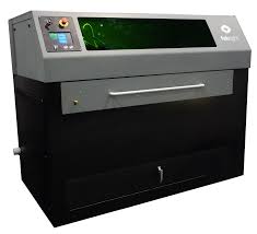
FabLight FL4500 is a versatile and powerful laser cutter that is capable of engraving and cutting sheet and tube metal. It will cut and engrave on square, rectangle, and round tubes up to 2" diameter as well as sheet metal. Internal features on tubing such as complex holes, slots, notches, and other features along the tube are also very easy to cut. It is equipped with an industrial-quality IPG fiber laser and precise mechanical control, you can make just about anything metal you can think of, including: custom signs, furniture, panels, enclosures, industrial components, jewelry & art.
Documentation
Terminology
- Engrave - Removes a thin layer of material from the surface of the metal along an established line. This has great accuracy but only produces a thin line.
- Raster - Very similar to an engrave but a raster is used to engrave a large area by passing over the area repeatedly. This works great for things like lettering and designs, but it does lose a little accuracy around the edges.
- FabCreator - The software used to set up a cut from a DXF.
User Manual
FabLight Metal Laser Cutter User Manual
3D Fab SolidWorks Plugin Manual
Training
Operation
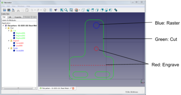
The Fablight is a simple machine to use for cutting flat stock. A part is saved as a DXF file and then imported to FabCreater where features can be set to cut, engrave, raster, or just be reference geometry. In FabCreator, the material properties are set and tabs are added - so that the material doesn't fall to the bottom of the machine. Once the part is set up correctly it is saved to a USB drive to be transferred to the machine. Most of the interactions with the machine happen through the touchscreen which makes previewing and cutting the job a simple task. Cutting tube stock is more intricate. The Fablight Solidworks Plugin is used to make a 2D DXF out of the 3D Solidworks model by essentially unwrapping the tube until it is one flat piece. This DXF is then wrapped back up into a 3D part in FabCreater before being sent to the machine. Only use the Fablight Solidworks Plugin when cutting or engraving tube stock. When cutting tube stock you will want to cut as close to the chuck as possible to avoid waste.
Demonstration
For the demonstration, you are required to engrave your own design on flat stock. This design should include a cut, engrave and raster. If no design is available use a George Fox logo.
General Procedure
For Flat Stock:
Setting up the file:
- Export the desired part as a DXF (a DWG will also work). It does not matter what software was used to create it as long as it can be exported as a DXF.
- Open the FabCreater software.
- Import the DXF using [File] > [Import] and make sure to select the correct units when prompted.
- Go to the [Edit] tab to select and delete any unwanted lines.
- Alternatively, line types can be adjusted in the [Part] tab to be cut, engraved, a raster, or a reference line. This can be helpful to see what the entire part looks like if when you are cutting a smaller piece for it.
- Go to the [Properties] tab and select the correct material properties such as material type, thickness, and stock type.
- While in the [Properties] tab, select the [Move to Origin] option to properly align the part where the laser will begin cutting. If there are multiple parts, align one with the origin and then orient the rest based on that.
- Hit [Accept].
- If there are any small parts, tabs can be added to prevent them from falling through the rack by going to the [Process] tab and the clicking the [Tabs] button.
- Save the file to a USB drive by going to [Job] > [Make]. Note: Make sure this is not saved in a folder of the USB drive so the laser can find the job.
Setting up the laser cutter:
- Slowly open the nitrogen canister so that the system is not filled to quickly and then adjust the regulator to 150 psi. Do not exceed 150 psi because the pressure in the canister is enough to rupture the hose to the machine.
- Turn on the Fablight by flipping the switch found on the left side of the machine and then turning the key.
- Once it is on select the machine home feature on the touchscreen to move the laser head to its starting position.
- Open the door on the front of the machine and check that the adjustable chuck is slid all the way to the right so the material tray will not hit it.
- Slide out the material tray so that the cutting material can be loaded.
- Place the cutting material anywhere on the tray and slide the tray back in. Make sure a click is heard to signify that the tray is in the correct position. There are two places where it will click you want to stop at the first one. The second one is at the very back of the machine and is where the tray goes when using the chuck.
- Close the door.
Performing the cut:
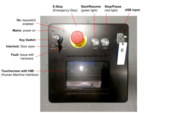
- Insert the USB drive on the right side of the panel. [not to be confused with the "Key Switch key"]
- Using the touch screen, press [New Job] > your file name > [Select Job]. A preview window will then open up where the model can be checked to make sure everything is correct.
- Hit the green checkmark to exit the preview.
- Hit the green checkmark again to move to the next step.
- Set the origin by moving the x and y slider bars. The laser head will move with the sliders and the exact position can be seen by the red guide laser. The location of the red dot will be the origin used in the FabCreater software and it should be placed where the use of material can be maximized (usually the corner of the material, furthest away from the chuck.).
- Press [Run Job] on the touchscreen.
- Press the [Start] button to the top of the touchscreen to begin the cut.
- Once the cut is completed wait a minute or so to let fumes dissipate and the material to cool.
- Remove the material from the machine using the door on the front.
Reset the Space
Here is how you can reset the space for the Metal Laser Cutter. Always reset the space!!!
- Turn off the machine.
- Turn off the compressed air.
- Turn off the exhaust switch.
- Ask the technician if you should complete a general cleaning of the machine and check the video linked in the general maintenance section of the Metal Laser Cutter wiki page.
Cut List
Approved Materials
- Steel
- Stainless steel
- Aluminum
DO NOT CUT
- Wood
- Plastics
- Fabrics
(Use the CO2 lasers for these materials.)
If you want to cut a material not listed here, please talk with the Maker Hub staff.
Certification
Complete the Machine Shop - Metal Laser Cutter Module at the link below to gain access to the Metal Laser Cutter. The Maker Hub Canvas course pertains to all facilities and equipment contained in the Maker Hub; simply complete the quizzes for the facilities/equipment you wish to use in the Maker Hub. Please email makerhub@georgefox.edu if you have any questions.
Troubleshooting
- The job runs but machine does not cut. Most likely the dry run process selected. Toggle dry run off.
- The machine does not cut, many sparks visible. The process table is not set correctly or the cutting head or optics are dirty. Ensure correct focal offset, cut speed, cut height, and gas pressure in process table. Check that the nozzle tip is clean, wipe off slag with Scotchbrite.
- Machine loses cut so that there crooked lines and gaps in the part. Again this is because the process table parameters14896 [Is this a true statement?]
- Incorrect or the cutting head/optics are dirty. Verify cut process parameters including cut speed, cut height, and gas pressure. Check nozzle tip is clean, wipe off slag with Scotchbrite.
- Cut does not go all the way through material. Select correct process. Reduce cut speed. Increase assist gas pressure up to 145 PSI. Verify process table is correct. Verify beam centering and focus test. Inspect nozzle tip.
- If your machine has a rotary you may encounter two homing errors. If the touchscreen says, “Idler (the chuck that holds the right side of the tube) not homed. Move idler to home”, open the door and move the idler all the way to the right. There is a sensor that detects when the idler is in its home position. Once the idler is in the home position, close the message and repress HOME THE MACHINE. If you encounter an error message saying that the rotary is locked; simply pull out the red pin, close the message, and repress HOME THE MACHINE.
Maintenance
General maintenance
Just like any other machine tool, the FabLight must be cleaned regularly for optimal performance. Lack of regular preventive maintenance (PM) will lead to damaged machine components, a reduction in part quality, and machine downtime. Cleaning the entire machine takes on average 10 minutes to complete and is easy to do with a single person. Even if the machine does not appear to be dirty, over time metal particles can build up; for optimum machine performance you must adhere to the recommended PM schedule, even if the machine “does not appear to be dirty.”
Specific Maintenance Tasks
| Maintenance Procedure | Frequency | Done By | Last Done | |
|---|---|---|---|---|
| 1 | General Cleaning | Every 1-2 Weeks depending on usage rate | Student | N/A |
| 2 | Clean Window | Once a month | Ace | |
| 3 | Lubricate drawer slides | Quarterly | Ace | |
| 4 | Apply WD-40 to rails | Quarterly | Ace | |
| 5 | Empty clean out drawer | Once a month | Ace |
- Vacuum out entire machine and wipe down the encoder strips with a paper towel. See this video for details. Also wipe off the cutting head with a paper towel.
- Wipe down the inside of the window with a microfiber cloth, not the vacuum or a paper towel.
- Apply grease to the drawer slides to keep them operating smoothly.
- Spray the rails with WD-40 to lubricate and keep them clean.
- Open the drawer, remove any large parts by hand, and then vacuum out the rest.


