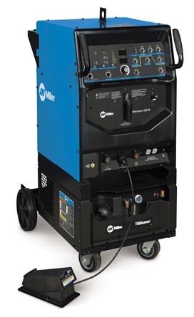
TIG Welder
Make: Miller
Model: Syncrowave 250DX
Ace: Wyatt Bertis (wbertis22@georgefox.edu).
Location: Welding Shop
Description
TIG stands for tungsten inert gas and is technically called gas tungsten arc welding (GTAW). The process uses a tungsten electrode located in a hand held torch that delivers the current to the welding arc. The tungsten and weld puddle are shielded and cooled with argon gas. A filler rod is used to manually add material to the weld puddle. During the welding process the tungsten should never touch the work piece. When this happens you will need to remove the tungsten and regrind the tip. Some of the advantages of this type of welding include strong high quality welds and many material options. One disadvantages of TIG welding is the speed is much slower compared to some of the other welding methods.
Here is an example of TIG welding and some good basic information.
Documentation
Terminology
- Squarewave technology was developed by Miller Electric in 1976 to improve your weld quality and make TIG (tungsten inert gas) welding easier. Miller Squarewave technology provides arc stability when welding aluminum, prevents arc rectification and eliminates tungsten erosion.
- CFH-Cubic Feet Per Hour
- Balance control-The balance control is adjustable to provide additional oxide removal (more cleaning) or less cleaning based on the condition of the material being welded.
- Syncro Start-This allows the choice of Soft, Standard or Hot TIG starts based on the application, lead lengths and tungsten size.
- Digital welding meters-Display both amperage and voltage for viewing of the actual and preset values for greater accuracy and repeatability in your welding procedure.
- Last procedure recall-Simplifies changing your Syncrowave back and forth from aluminum TIG to stainless TIG to Stick welding. One switch makes all the control panel changes.
- Adaptive Hot Start-Stick welding features such as Adaptive Hot Start™ provide good arc strikes without sticking. Once welding, the DIG control makes dynamic adjustments to the welder to ensure smooth E7018 and deep penetration E6010.
Training
Operation
Here are some general setup rules of thumb:
- The CFH gas setting should be roughly 2x the weld cup size. If you were to use a #7 cup the gas flow should be set to 14 CFH.
- The tungsten stick-out from the cup should be no more than the cup diameter. Using a #7 cup would allow for a maximum tungsten stick-out of 7/16"
Demonstration
Demonstrate you can safely setup the saw and rip a board. You will then proceed to cross cut one of the remaining pieces. Remember to set the blade height so it is protruding less than 1/8" out the top of material for less exposure. When performing a rip cut the fence is used to guide the lumber into the blade. You want to make sure that the distance between the fence and blade is the width of desired cut. Mark the edge of the material when doing a cross cut so you can align the material with the blade in the sled. You can also use a miter gauge for making cross cuts but make sure the material is long enough and well supported.
General Procedure
- Place the fume hood over the area you will be welding
- Select electrode that is adequate for your application of material
- Grind electrode to a point. (This gives a smaller and more directed arc)
- Insert the electrode into the collet of the torch
- Attach ground clamp to table (ensure ground contact surface is clean)
- Ensure the adjusting screw on the tank regulator is loose (Do not unscrew all the way)
- Open cylinder valve all the way
- Turn the adjusting screw (clockwise) to increase flow to 15 CFH. The gas will only flow after the pedal is depressed and will stop after the post-flow time has been reached.
- Identify material type, and thickness that is going to be welded
- Refer to TIG welding chart for specified adjustments, specific to your application
- Clean material to remove any oxidizing and or oil residue
- Turn on the welder and adjust----------
- Hold the electrode in your dominant hand (ensure it can move freely)
- Hold electrode about an 1/8 inch away from the metal
- Using the foot pedal to control the voltage, start off with the foot pedal half way down to start a puddle on the material.
- Once a puddle is started let off the foot pedal to maintain a steady puddle without burning through the material.
- Once the puddle is formed, dab the filler rod into the puddle
- Moving along the material, walk the electrode back and forth across the puddle while dabbing the filler into the pool
- Shutting down:
- Close gas cylinder valve
- Back out adjusting screw on regulator (Do Not unscrew all the way)
- Turn off the welder
- Remove ground clamp
Safety
- Don't exceed gas pressure past specified value
- Don't weld with gas off
- Always use a welding helmet and proper PPE
- Don't weld in wet gear or standing water
- Don't unscrew regulator adjusting screw all the way out
- Make sure ground clamp is connected to work
Certification
Troubleshooting
Maintenance
General maintenance
The welding torch and cables should be inspected on a regular basis. Look for any signs of cracking or cuts in the cables.
Specific Maintenance Tasks
| Maintenance Procedure | Frequency | Done By |
|---|---|---|
| Check Argon Pressure | Before Use | Student/Tech |
| Check Coolant Flow | Before Use | Student/Tech |
| Inspect collet & Cup | Before Use | Student/Tech |

