Difference between revisions of "MIG Welder"
Jump to navigation
Jump to search
| Line 19: | Line 19: | ||
* [ https://www.millerwelds.com/files/owners-manuals/o1325a_mil.pdf ] | * [ https://www.millerwelds.com/files/owners-manuals/o1325a_mil.pdf ] | ||
| − | = | + | = Procedures: = |
| − | + | ||
| + | '''Procedures:''' | ||
| + | |||
| + | Prior to Welding | ||
| + | # Place the fume hood over the area you will be welding at | ||
| + | # Attach the ground clamp to the bench your workpiece will be on | ||
| + | # Ensure the workpiece is touching the conductive surface of the table | ||
| + | # Ensure the adjusting screw on the tank regulator is loose (Do not unscrew all the way) | ||
| + | # Open cylinder valve all the way | ||
| + | # Turn the adjusting screw (clockwise) to increase pressure to 15 CFH. | ||
| + | # Identify material type and thickness that is going to be welded | ||
| + | # Refer to MIG welding chart for specified adjustments, specific to your application | ||
| + | # Turn on the welder and adjust wire speed and voltage | ||
| + | # Ensure you are wearing all necessary protective gear | ||
| + | # Ensure the welding torch has proper amount of wire protruding from tip (about ¼ inch) If too long, trim excess with the welding pliers. | ||
| + | # Weld! | ||
| + | |||
| + | After Welding | ||
| + | # Close gas cylinder valve | ||
| + | # Bleed remaining gas by depressing trigger until regulator drops to 0 | ||
| + | # Back out adjusting screw on regulator (Do Not unscrew all the way) | ||
| + | # Turn off the welder | ||
| + | # Remove ground clamp | ||
Revision as of 14:04, 11 February 2019
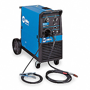
The Millermatic 210 is a wire feed welder that is meant for light industrial use. It uses 72/25 CO2 and Argon gas mixture to shield the molten weld from oxygen. If the weld pool is exposed to oxygen, it can create a handful of problems such as porosity and excessive spatter in the bead. This welder is capable of welding carbon steel as well as stainless steel.
Documentation
Procedures:
Procedures:
Prior to Welding
- Place the fume hood over the area you will be welding at
- Attach the ground clamp to the bench your workpiece will be on
- Ensure the workpiece is touching the conductive surface of the table
- Ensure the adjusting screw on the tank regulator is loose (Do not unscrew all the way)
- Open cylinder valve all the way
- Turn the adjusting screw (clockwise) to increase pressure to 15 CFH.
- Identify material type and thickness that is going to be welded
- Refer to MIG welding chart for specified adjustments, specific to your application
- Turn on the welder and adjust wire speed and voltage
- Ensure you are wearing all necessary protective gear
- Ensure the welding torch has proper amount of wire protruding from tip (about ¼ inch) If too long, trim excess with the welding pliers.
- Weld!
After Welding
- Close gas cylinder valve
- Bleed remaining gas by depressing trigger until regulator drops to 0
- Back out adjusting screw on regulator (Do Not unscrew all the way)
- Turn off the welder
- Remove ground clamp
