Difference between revisions of "Quena"
(→CAD) |
|||
| (11 intermediate revisions by the same user not shown) | |||
| Line 2: | Line 2: | ||
|Is tv=True | |Is tv=True | ||
|Has name={{PAGENAME}} | |Has name={{PAGENAME}} | ||
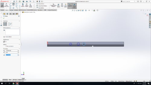
| − | |Has icon=File: | + | |Has icon=File:Quena2_20.png |
| − | |Has icondesc= | + | |Has icondesc=quena Icon |
| − | |Has image=File: | + | |Has image=File:Quena2_20.png |
| − | |Has description= | + | |Has description=quena |
| − | |||
| − | |||
|Uses software=Solidworks | |Uses software=Solidworks | ||
| Line 17: | Line 15: | ||
In this TV, we will be creating a quena. | In this TV, we will be creating a quena. | ||
| + | |||
| + | == Bill of Materials == | ||
| + | |||
| + | * 1/2" PVC | ||
| + | * 3D printed parts | ||
==CAD== | ==CAD== | ||
| − | + | ||
Step 1: Open SolidWorks 2020, and select a new part. Don't forget to save your file frequently as you go. In the bottom-right corner of your Solidworks window, change the units from IPS to MMGS (milimeter, gram, second) | Step 1: Open SolidWorks 2020, and select a new part. Don't forget to save your file frequently as you go. In the bottom-right corner of your Solidworks window, change the units from IPS to MMGS (milimeter, gram, second) | ||
| − | Step 2: Select the | + | Step 2: Select the Front Plane in the design tree (the left column on your screen) to begin your sketch. Click on the Sketch tab above and click Sketch. |
[[Image:Quena_1.png|500px]] | [[Image:Quena_1.png|500px]] | ||
| − | |||
| − | |||
Step 3: Draw out the shape below. Start the lower left corner on the origin (the red arrows), and make sure the lines snap to horizontal and vertical. | Step 3: Draw out the shape below. Start the lower left corner on the origin (the red arrows), and make sure the lines snap to horizontal and vertical. | ||
Using the smart dimension tool, which you can get either on the menu at top, or by holding your right mouse button and dragging up. | Using the smart dimension tool, which you can get either on the menu at top, or by holding your right mouse button and dragging up. | ||
If done correctly, the entire sketch should be black, indicating that it is fully defined. | If done correctly, the entire sketch should be black, indicating that it is fully defined. | ||
| + | |||
| + | [[Image:Quena_2.png|500px]] | ||
| + | |||
| + | Step 4: In the top left corner, click Exit Sketch (your sketch should turn light grey). Click on the Features tab and select the Revolved Boss/Base option. Click on the "axis of revolution" box, and select the bottom line. | ||
| + | The preview should match the picture below. | ||
| + | |||
| + | Click the green checkmark in the left column if everything looks good. | ||
| + | |||
| + | [[Image:Quena_3.png|500px]] | ||
| + | |||
| + | Step 5: Select the Front Plane in the design tree (the left column on your screen) to begin a new sketch. Click on the Sketch tab above and click Sketch. | ||
| + | |||
| + | [[Image:Quena_4.png|500px]] | ||
| + | |||
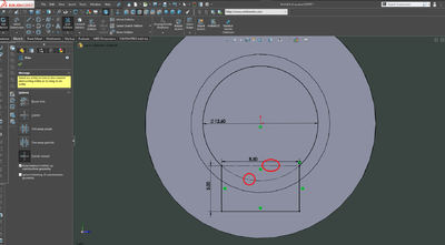
| + | Step 6: On the new sketch, select the ‘Ellipse’ option to draw the same shape as the screenshot. Place the corner of the eclipse on the corner of the object, and add dimensions to constrain it. | ||
| + | |||
| + | [[Image:Quena_4.5.png|500px]] | ||
| + | |||
| + | Step 7: Click on the Features tab and select the ‘Extruded Cut’ option. Select ‘Through All- Both’. Click the green checkmark in the left column if everything looks good like the screenshot. | ||
| + | |||
| + | [[Image:Quena_5.png|500px]] | ||
| + | |||
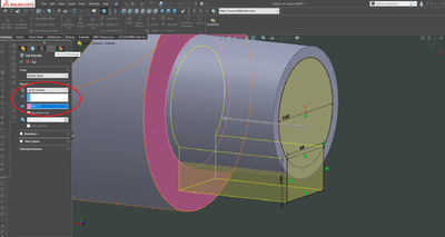
| + | Step 8: Right Click the ‘Blue Circle’ (see screenshot) on the object and select ‘normal to’ and again select ‘new sketch’ option after. | ||
| + | |||
| + | Step 8: Select the round end face, and create a new sketch. To make that sketch become parallel to the screen, press space, and click on the appropriate face of the cube. | ||
| + | |||
| + | [[Image:Quena_6.png|500px]] | ||
| + | |||
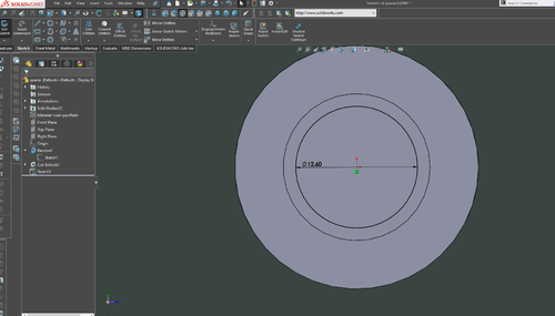
| + | Step 9: In the New Sketch draw a circle, with it's center on the origin. Add a dimension, and set it's value to 12.6mm | ||
| + | |||
| + | [[Image:Quena_7.png|500px]] | ||
| + | |||
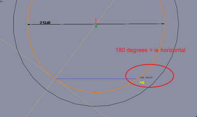
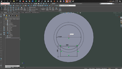
| + | Step 10: Nest, use the line tool to draw a rectangle as shown in the picture. Make sure the ends of the top line are on the circle, and that the line is horizontal. | ||
| + | Draw the others to form a rectangle. | ||
| + | |||
| + | [[Image:Quena_8.png|400px]] | ||
| + | [[Image:Quena_9.png|400px]] | ||
| + | |||
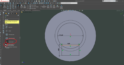
| + | Next, select the "trim entities" tool on the top bar. Select "trim to closest", and make sure "keep trimmed entities as construction geometry" is checked. | ||
| + | |||
| + | [[Image:Quena_10.png|400px]] | ||
| + | |||
| + | Trim the 2 inside lines, so that the solid lines form 1 loop. | ||
| + | |||
| + | [[Image:Quena_11.png|400px]] | ||
| + | |||
| + | Step 12: Click on the Features tab and select the ‘Extruded Cut’ option. under "direction 1", select "up to surface" for the depth of the cut. Select the pink face as the surface. | ||
| + | |||
| + | [[Image:Quena_12.png|400px]] | ||
| + | |||
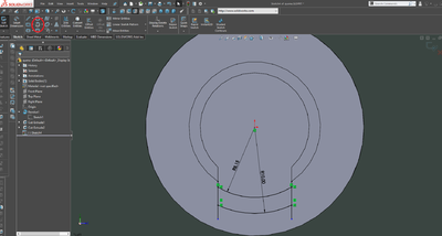
| + | Step 13: Next, create a new sketch on that pink face. on this face, draw 2 lines vertically down from the sides of the notch, and then connect them with 2 arcs. The arc tool is circled in red in the upper left corner. | ||
| + | Dimension the arcs as shown. | ||
| + | |||
| + | [[Image:Quena_13.png|400px]] | ||
| + | |||
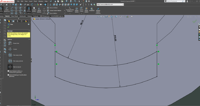
| + | Step 14: Next, use the trim tool from earlier to reduce the sketch down to a single loop. | ||
| + | For the upper parts of the 2 vertical lines, trim them to construction geometry. This preserves the relation between the lines and the notch. | ||
| + | For the lower part of the lines, uncheck the "keep trimmed entities as construction geometry" box, and it will delete the overhanging part of the line. | ||
| + | |||
| + | [[Image:Quena_14.png|400px]] | ||
| + | |||
| + | Step 15: Now, extrude cut with this sketch. the cut should go all the way through | ||
| + | |||
| + | [[Image:Quena_15.png|400px]] | ||
| + | |||
| + | And you're done! | ||
| + | |||
| + | |||
| + | ==3D printing== | ||
| + | |||
| + | For instructions on using the 3D printers, see the prusa page [[Prusa_3D_Printer]] | ||
| + | |||
| + | The part prints best if printed upright, and with supports under the overhang. | ||
| + | |||
| + | [[Image:Quena_16.png|500px]] | ||
| + | |||
| + | |||
| + | ==Body Cad== | ||
| + | |||
| + | Step 1: Open SolidWorks 2020, and select a new part. Don't forget to save your file frequently as you go. In the bottom-right corner of your Solidworks window, change the units to CGS (Centimeter, gram, second). Select the Right Plane in the design tree (the left column on your screen) to begin your sketch. Click on the Sketch tab above and click Sketch. | ||
| + | |||
| + | [[Image:Quena2_1.png|500px]] | ||
| + | |||
| + | Step 2: Make a horizontal line starting from the origin. Then use the smart dimension tool to make it 40cm long. Click the green checkmark in the left column if everything looks good like the screenshot. | ||
| + | |||
| + | [[Image:Quena2_2.png|500px]] | ||
| + | |||
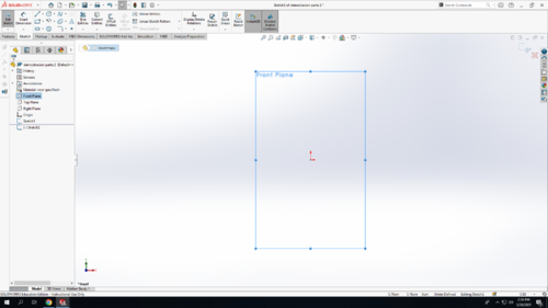
| + | Step 3: Select the Front Plane in the design tree (the left column on your screen) to begin your new sketch. Click on the Sketch tab above and click Sketch. | ||
| + | |||
| + | [[Image:Quena2_3.png|500px]] | ||
| + | |||
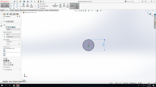
| + | Step 4: Select the ‘Circle’ option to draw a circle starting at the origin. Using the ‘smart dimension’ tool make the radius of the circle the same as the screenshot below. Click the green checkmark in the left column if everything looks good like the screenshot. | ||
| + | |||
| + | [[Image:Quena2_4.png|500px]] | ||
| + | |||
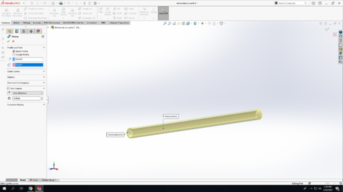
| + | Step 5: Click on the Features tab and select the ‘Sweep Boss/Base’ option. Under ‘Profile and Path’ select ‘sketch profile’ and for the end circle (blue color) select the sketch of the circle (sketch2). For the line (pink color) select the straight line sketch (sketch 1). In addition, add the ‘thin feature’. Select one direction and make the thickness of it be 0.29 cm as shown in the screenshot. Click the green checkmark in the left column if everything looks good like the screenshot. | ||
| + | |||
| + | [[Image:Quena2_5.png|500px]] | ||
| + | |||
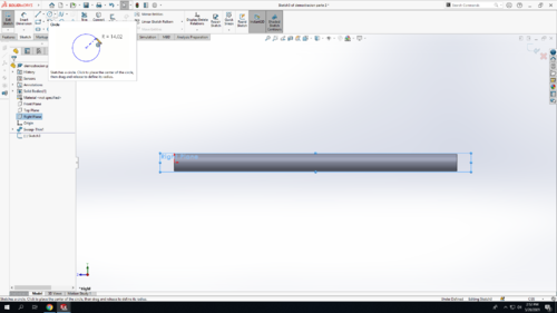
| + | Step 6: Select the Right Plane in the design tree (the left column on your screen) to begin your new sketch. | ||
| + | |||
| + | [[Image:Quena2_6.png|500px]] | ||
| + | |||
| + | Step 7: Start drawing circles with the ‘circle’ option. Little advice, make sure the center of your circles are aligned with the origin (you will see blue dotted lines). Create 6 circles in the same sketch. | ||
| + | |||
| + | [[Image:Quena2_7.png|500px]] | ||
| + | |||
| + | Step 8: Using the ‘Smart Dimension’ option make the diameters of the circles the same as shown in the screenshot below. In addition, make the distances starting from the origin point to each center of a circle identical as the screenshot. Click the green checkmark in the left column if everything looks good like the picture below. | ||
| + | |||
| + | [[Image:Quena2_8.png|500px]] | ||
| + | |||
| + | Step 9: Click on the Features tab and select the ‘Extruded Cut’ option. Select ‘Up to next’ under direction1’. If the grey arrow is pointing the opposite side, you can always switch direction by clicking the icon next to the ‘Up to next’. Click the green checkmark in the left column if everything looks good like the screenshot. | ||
| + | |||
| + | [[Image:Quena2_9.png|500px]] | ||
| + | |||
| + | Step 10: Select the Right Plane in the design tree (the left column on your screen) to start your new sketch. Click on the Sketch tab above and click Sketch. We will be using the ‘circle’ option. | ||
| + | |||
| + | [[Image:Quena2_10.png|500px]] | ||
| + | |||
| + | Step 11: Draw a circle making sure the center of your circles are aligned with the origin (you will see blue dotted lines). See image below. | ||
| + | |||
| + | [[Image:Quena2_11.png|500px]] | ||
| + | |||
| + | Step 12: Using the ‘smart dimension’ option, make the distance starting from the origin point to the center of the circle identical as the screenshot. Also, make the diameter of the circle the same as shown below. Click the green checkmark in the left column if everything looks good. | ||
| + | |||
| + | [[Image:Quena2_12.png|500px]] | ||
| + | |||
| + | Step 12: Click on the Features tab and select the ‘Extruded Cut’ option. Select ‘Up to next’ under direction1’. If the grey arrow is pointing the opposite side, you can always switch direction by clicking the icon next to the ‘Up to next’. Click the green checkmark in the left column if everything looks good like the screenshot. | ||
| + | |||
| + | [[Image:Quena2_13.png|500px]] | ||
| + | |||
| + | Step 14: Select the Front Plane in the design tree (the left column on your screen) to start your new sketch. Click on the Sketch tab above and click Sketch. | ||
| + | |||
| + | [[Image:Quena2_14.png|500px]] | ||
| + | |||
| + | Step 14: Make a vertical centerline using the ‘centerline’ option. This can be found by clicking on the arrow next to the line icon. Then use the ‘line’ option to draw the same line as the screenshot (outer circle). Click the green checkmark in the left column if everything looks good like the screenshot. | ||
| + | |||
| + | [[Image:Quena2_15.png|500px]] | ||
| + | |||
| + | Step 16: Having the last Sketch selected, go under ‘Features’ and select ‘Reference Geometry’. Once you click on the little triangle to see sub-options, and select ‘plane’. You just created a plane! | ||
| + | |||
| + | [[Image:Quena2_16.png|500px]] | ||
| + | |||
| + | Step 17: At this point, we need to make the plane fully defined. First, under ‘first reference’ select the vertical line you just created in the last step. Second, under ‘second reference’ select the area between the 2 circles (See screenshot - purple area). Now, right under the coincident option, you will see an angle symbol. In that box type either “26 deg” or “154 deg”. This will depend on which side the plane is leaning. Ideally, we want to have a small angle close to the top of the quena which is where the 6 holes are at! Click the green checkmark in the left column if everything looks good like the screenshot. | ||
| + | |||
| + | [[Image:Quena2_17.png|500px]] | ||
| + | [[Image:Quena2_17.5.png|500px]] | ||
| + | |||
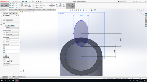
| + | Step 18: On that plane you just created select ‘normal to’ and click on the Sketch tab above and click Sketch to create a new one. On the new sketch, select the ‘Ellipse’ option to draw the same shape as the screenshot. Make sure the oval has the same dimension given in the screenshot. | ||
| + | |||
| + | [[Image:Quena2_18.png|500px]] | ||
| + | |||
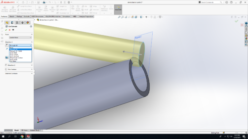
| + | Step 19: Click on the Features tab and select the ‘Extruded Cut’ option. Select ‘All Through’ under direction1’. If the grey arrow is pointing the opposite side, you can always switch direction by clicking the icon next to the ‘Up to next’. Click the green checkmark in the left column if everything looks good like the screenshot. | ||
| + | |||
| + | [[Image:Quena2_19.png|500px]] | ||
| + | |||
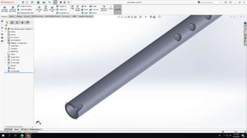
| + | Step 20: You did it! Save your work! You should now have something that looks like the screenshot below. | ||
| + | |||
| + | [[Image:Quena2_20.png|500px]] | ||
Latest revision as of 07:36, 14 June 2021
In this TV, we will be creating a quena.
Bill of Materials
- 1/2" PVC
- 3D printed parts
CAD
Step 1: Open SolidWorks 2020, and select a new part. Don't forget to save your file frequently as you go. In the bottom-right corner of your Solidworks window, change the units from IPS to MMGS (milimeter, gram, second)
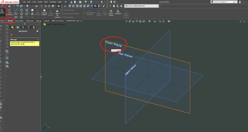
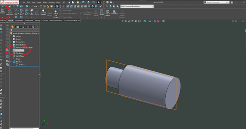
Step 2: Select the Front Plane in the design tree (the left column on your screen) to begin your sketch. Click on the Sketch tab above and click Sketch.
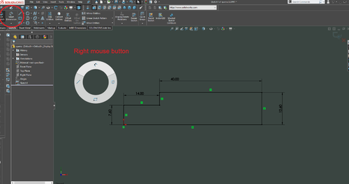
Step 3: Draw out the shape below. Start the lower left corner on the origin (the red arrows), and make sure the lines snap to horizontal and vertical. Using the smart dimension tool, which you can get either on the menu at top, or by holding your right mouse button and dragging up. If done correctly, the entire sketch should be black, indicating that it is fully defined.
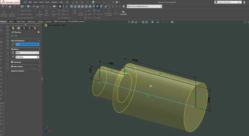
Step 4: In the top left corner, click Exit Sketch (your sketch should turn light grey). Click on the Features tab and select the Revolved Boss/Base option. Click on the "axis of revolution" box, and select the bottom line. The preview should match the picture below.
Click the green checkmark in the left column if everything looks good.
Step 5: Select the Front Plane in the design tree (the left column on your screen) to begin a new sketch. Click on the Sketch tab above and click Sketch.
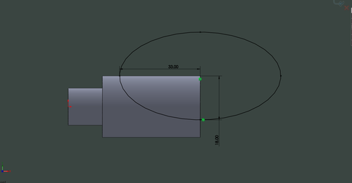
Step 6: On the new sketch, select the ‘Ellipse’ option to draw the same shape as the screenshot. Place the corner of the eclipse on the corner of the object, and add dimensions to constrain it.
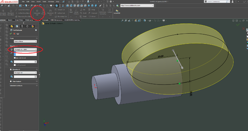
Step 7: Click on the Features tab and select the ‘Extruded Cut’ option. Select ‘Through All- Both’. Click the green checkmark in the left column if everything looks good like the screenshot.
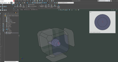
Step 8: Right Click the ‘Blue Circle’ (see screenshot) on the object and select ‘normal to’ and again select ‘new sketch’ option after.
Step 8: Select the round end face, and create a new sketch. To make that sketch become parallel to the screen, press space, and click on the appropriate face of the cube.
Step 9: In the New Sketch draw a circle, with it's center on the origin. Add a dimension, and set it's value to 12.6mm
Step 10: Nest, use the line tool to draw a rectangle as shown in the picture. Make sure the ends of the top line are on the circle, and that the line is horizontal. Draw the others to form a rectangle.
Next, select the "trim entities" tool on the top bar. Select "trim to closest", and make sure "keep trimmed entities as construction geometry" is checked.
Trim the 2 inside lines, so that the solid lines form 1 loop.
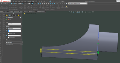
Step 12: Click on the Features tab and select the ‘Extruded Cut’ option. under "direction 1", select "up to surface" for the depth of the cut. Select the pink face as the surface.
Step 13: Next, create a new sketch on that pink face. on this face, draw 2 lines vertically down from the sides of the notch, and then connect them with 2 arcs. The arc tool is circled in red in the upper left corner. Dimension the arcs as shown.
Step 14: Next, use the trim tool from earlier to reduce the sketch down to a single loop. For the upper parts of the 2 vertical lines, trim them to construction geometry. This preserves the relation between the lines and the notch. For the lower part of the lines, uncheck the "keep trimmed entities as construction geometry" box, and it will delete the overhanging part of the line.
Step 15: Now, extrude cut with this sketch. the cut should go all the way through
And you're done!
3D printing
For instructions on using the 3D printers, see the prusa page Prusa_3D_Printer
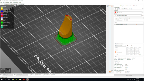
The part prints best if printed upright, and with supports under the overhang.
Body Cad
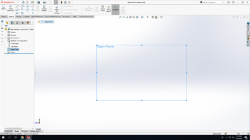
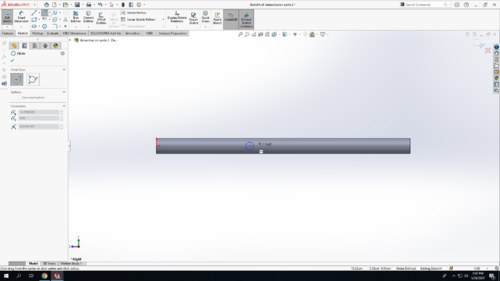
Step 1: Open SolidWorks 2020, and select a new part. Don't forget to save your file frequently as you go. In the bottom-right corner of your Solidworks window, change the units to CGS (Centimeter, gram, second). Select the Right Plane in the design tree (the left column on your screen) to begin your sketch. Click on the Sketch tab above and click Sketch.
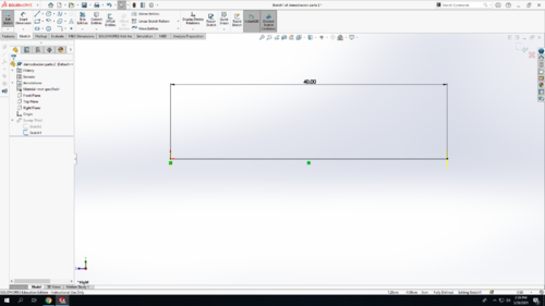
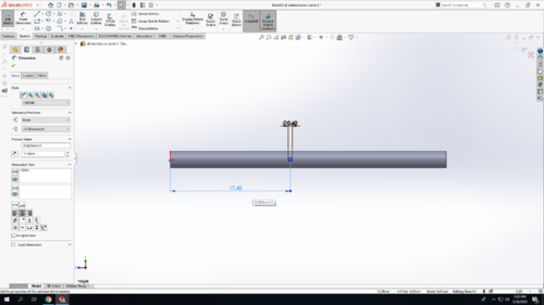
Step 2: Make a horizontal line starting from the origin. Then use the smart dimension tool to make it 40cm long. Click the green checkmark in the left column if everything looks good like the screenshot.
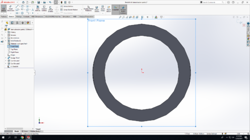
Step 3: Select the Front Plane in the design tree (the left column on your screen) to begin your new sketch. Click on the Sketch tab above and click Sketch.
Step 4: Select the ‘Circle’ option to draw a circle starting at the origin. Using the ‘smart dimension’ tool make the radius of the circle the same as the screenshot below. Click the green checkmark in the left column if everything looks good like the screenshot.
Step 5: Click on the Features tab and select the ‘Sweep Boss/Base’ option. Under ‘Profile and Path’ select ‘sketch profile’ and for the end circle (blue color) select the sketch of the circle (sketch2). For the line (pink color) select the straight line sketch (sketch 1). In addition, add the ‘thin feature’. Select one direction and make the thickness of it be 0.29 cm as shown in the screenshot. Click the green checkmark in the left column if everything looks good like the screenshot.
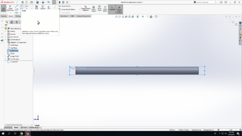
Step 6: Select the Right Plane in the design tree (the left column on your screen) to begin your new sketch.
Step 7: Start drawing circles with the ‘circle’ option. Little advice, make sure the center of your circles are aligned with the origin (you will see blue dotted lines). Create 6 circles in the same sketch.
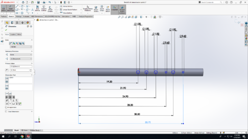
Step 8: Using the ‘Smart Dimension’ option make the diameters of the circles the same as shown in the screenshot below. In addition, make the distances starting from the origin point to each center of a circle identical as the screenshot. Click the green checkmark in the left column if everything looks good like the picture below.
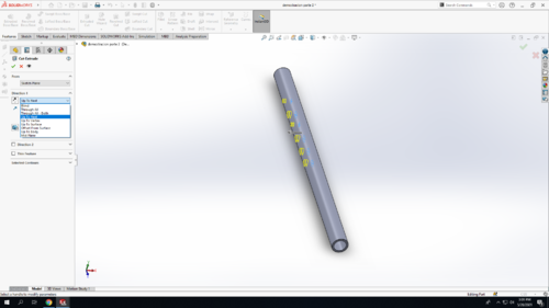
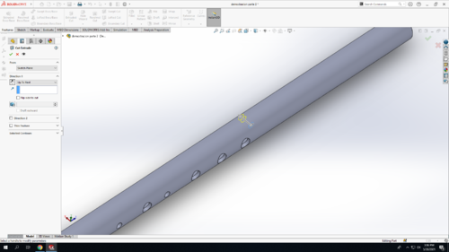
Step 9: Click on the Features tab and select the ‘Extruded Cut’ option. Select ‘Up to next’ under direction1’. If the grey arrow is pointing the opposite side, you can always switch direction by clicking the icon next to the ‘Up to next’. Click the green checkmark in the left column if everything looks good like the screenshot.
Step 10: Select the Right Plane in the design tree (the left column on your screen) to start your new sketch. Click on the Sketch tab above and click Sketch. We will be using the ‘circle’ option.
Step 11: Draw a circle making sure the center of your circles are aligned with the origin (you will see blue dotted lines). See image below.
Step 12: Using the ‘smart dimension’ option, make the distance starting from the origin point to the center of the circle identical as the screenshot. Also, make the diameter of the circle the same as shown below. Click the green checkmark in the left column if everything looks good.
Step 12: Click on the Features tab and select the ‘Extruded Cut’ option. Select ‘Up to next’ under direction1’. If the grey arrow is pointing the opposite side, you can always switch direction by clicking the icon next to the ‘Up to next’. Click the green checkmark in the left column if everything looks good like the screenshot.
Step 14: Select the Front Plane in the design tree (the left column on your screen) to start your new sketch. Click on the Sketch tab above and click Sketch.
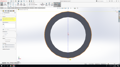
Step 14: Make a vertical centerline using the ‘centerline’ option. This can be found by clicking on the arrow next to the line icon. Then use the ‘line’ option to draw the same line as the screenshot (outer circle). Click the green checkmark in the left column if everything looks good like the screenshot.
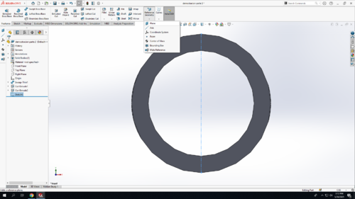
Step 16: Having the last Sketch selected, go under ‘Features’ and select ‘Reference Geometry’. Once you click on the little triangle to see sub-options, and select ‘plane’. You just created a plane!
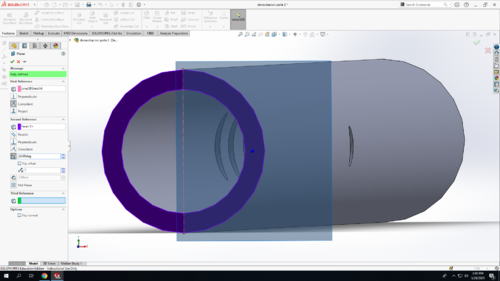
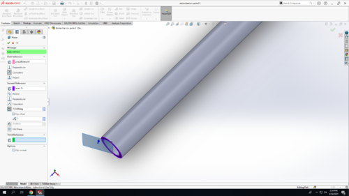
Step 17: At this point, we need to make the plane fully defined. First, under ‘first reference’ select the vertical line you just created in the last step. Second, under ‘second reference’ select the area between the 2 circles (See screenshot - purple area). Now, right under the coincident option, you will see an angle symbol. In that box type either “26 deg” or “154 deg”. This will depend on which side the plane is leaning. Ideally, we want to have a small angle close to the top of the quena which is where the 6 holes are at! Click the green checkmark in the left column if everything looks good like the screenshot.
Step 18: On that plane you just created select ‘normal to’ and click on the Sketch tab above and click Sketch to create a new one. On the new sketch, select the ‘Ellipse’ option to draw the same shape as the screenshot. Make sure the oval has the same dimension given in the screenshot.
Step 19: Click on the Features tab and select the ‘Extruded Cut’ option. Select ‘All Through’ under direction1’. If the grey arrow is pointing the opposite side, you can always switch direction by clicking the icon next to the ‘Up to next’. Click the green checkmark in the left column if everything looks good like the screenshot.
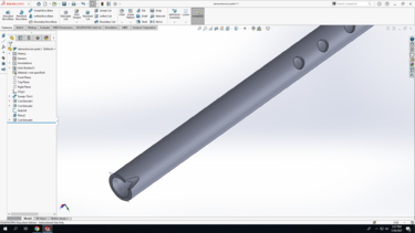
Step 20: You did it! Save your work! You should now have something that looks like the screenshot below.
