Difference between revisions of "Triangle"
Cpainter17 (talk | contribs) |
Arodgers24 (talk | contribs) |
||
| (15 intermediate revisions by one other user not shown) | |||
| Line 2: | Line 2: | ||
|Is tv=True | |Is tv=True | ||
|Has name={{PAGENAME}} | |Has name={{PAGENAME}} | ||
| − | |Has icon=File: | + | |Has icon=File:Triangle complete.png |
|Has icondesc=Egg Shaker Icon | |Has icondesc=Egg Shaker Icon | ||
| − | |Has image=File: | + | |Has image=File:Triangle complete.png |
| − | |Has description=Finished | + | |Has description=Finished Triangle |
|Uses equipment=Hand Bender | |Uses equipment=Hand Bender | ||
|Uses software=Solidworks | |Uses software=Solidworks | ||
| Line 13: | Line 13: | ||
[[{{#show: {{FULLPAGENAME}}|?Has image|link=none}}|375px|thumb|upright=1.5|{{#show: {{FULLPAGENAME}}|?Has imagedesc}}]] | [[{{#show: {{FULLPAGENAME}}|?Has image|link=none}}|375px|thumb|upright=1.5|{{#show: {{FULLPAGENAME}}|?Has imagedesc}}]] | ||
| − | |||
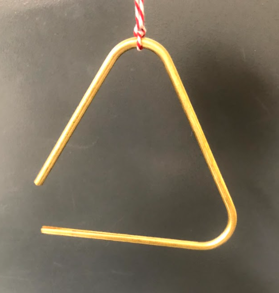
In this [[TV]], we will take you through the steps of drawing a Triangle in [[Solidworks|SolidWorks]] and fabricating it using the [[Hand Bender]]. | In this [[TV]], we will take you through the steps of drawing a Triangle in [[Solidworks|SolidWorks]] and fabricating it using the [[Hand Bender]]. | ||
| Line 21: | Line 20: | ||
<br> | <br> | ||
<br> | <br> | ||
| + | __TOC__ | ||
<br> | <br> | ||
<br> | <br> | ||
| Line 30: | Line 30: | ||
==SolidWorks== | ==SolidWorks== | ||
| − | <strong>Step 1:</strong> Open SolidWorks | + | <strong>Step 1:</strong> Open SolidWorks, and select a new part. Don't forget to save your file frequently as you go. In the bottom-right corner of your Solidworks window, set the units to MMGS (millimeter, gram, second). |
[[File:Triangle 1.png|1500px|none]] | [[File:Triangle 1.png|1500px|none]] | ||
| Line 44: | Line 44: | ||
<strong>Step 3:</strong> The first line is going to be centered at the origin. After selecting the line command, check the “midpoint line” box in the left panel. Where you select will become the location of the center of the line. Select the origin and draw a horizontal line. | <strong>Step 3:</strong> The first line is going to be centered at the origin. After selecting the line command, check the “midpoint line” box in the left panel. Where you select will become the location of the center of the line. Select the origin and draw a horizontal line. | ||
| − | [[File:Triangle 3.png|200px|none]] [[File:Triangle 4.png| | + | [[File:Triangle 3.png|200px|left|none]] [[File:Triangle 4.png|1400px|none]] |
| − | |||
| + | <br> | ||
Insert another line beginning at the end point of our current line and complete the triangle. At this point, the sides do not need to be perfect, just the general shape is needed. | Insert another line beginning at the end point of our current line and complete the triangle. At this point, the sides do not need to be perfect, just the general shape is needed. | ||
| − | [ | + | [[File:Triangle 5.png|1500px|none]] |
<br> | <br> | ||
| Line 55: | Line 55: | ||
<strong>Step 4:</strong> Using the Smart dimension tool, make the bottom side of the triangle 130 mm. | <strong>Step 4:</strong> Using the Smart dimension tool, make the bottom side of the triangle 130 mm. | ||
| − | [ | + | [[File:Triangle 6.png|1500px|none]] |
<br> | <br> | ||
| Line 62: | Line 62: | ||
Ctrl + select all of the lines making up the triangle. In the left panel under the “Add Relations” section, select “equal.” This will make all of the lengths equal, giving us the equilateral triangle we are aiming for. | Ctrl + select all of the lines making up the triangle. In the left panel under the “Add Relations” section, select “equal.” This will make all of the lengths equal, giving us the equilateral triangle we are aiming for. | ||
| − | [ | + | [[File:Triangle 7.png|200px|left]] |
| − | [ | + | [[File:Triangle 8.png|1400px|none]] |
| + | |||
<br> | <br> | ||
| Line 69: | Line 70: | ||
<strong>Step 6:</strong> A fillet will be used to achieve the rounded corners of our triangle. Select the “Sketch Fillet” command in the toolbar. This command creates a round corner between two lines. In the left panel, set the fillet parameter to have a radius of 12.7 mm (equivalent to our ½ die). | <strong>Step 6:</strong> A fillet will be used to achieve the rounded corners of our triangle. Select the “Sketch Fillet” command in the toolbar. This command creates a round corner between two lines. In the left panel, set the fillet parameter to have a radius of 12.7 mm (equivalent to our ½ die). | ||
| − | [ | + | [[File:Triangle 9.png|300px|none]] |
| + | <br> | ||
Select two adjacent sides of the triangle to create a round between them. Because of the relation we used, an alert will pop up; hit yes to continue and be sure to apply the fillet to each of the corners. Repeat this for each corner of the triangle. | Select two adjacent sides of the triangle to create a round between them. Because of the relation we used, an alert will pop up; hit yes to continue and be sure to apply the fillet to each of the corners. Repeat this for each corner of the triangle. | ||
| − | [ | + | [[File:Triangle 10.png|1500px|none]] |
| + | <br> | ||
A yellow line will preview the fillet on the triangle; if these lines appear correct hit the green check mark to apply the fillets. | A yellow line will preview the fillet on the triangle; if these lines appear correct hit the green check mark to apply the fillets. | ||
| − | [ | + | [[File:Triangle 11.png|1500px|none]] |
<br> | <br> | ||
<br> | <br> | ||
<strong>Step 7:</strong> The shape we are drawing is the guideline for the triangle. Since it needs an open corner, select one of the round edges and change it to a construction line. Exit the sketch. The shape should look like this: | <strong>Step 7:</strong> The shape we are drawing is the guideline for the triangle. Since it needs an open corner, select one of the round edges and change it to a construction line. Exit the sketch. The shape should look like this: | ||
| + | <br> | ||
| − | [ | + | [[File:Triangle 12.png|1500px|none]] |
<br> | <br> | ||
| Line 89: | Line 93: | ||
<strong>Step 8:</strong> Now we will be turning our lines into a 3D model. In the design tree, select the “Right Plane” and begin a new sketch | <strong>Step 8:</strong> Now we will be turning our lines into a 3D model. In the design tree, select the “Right Plane” and begin a new sketch | ||
| − | [ | + | [[File:Triangle 13.png|1500px|none]] |
<br> | <br> | ||
| Line 95: | Line 99: | ||
<strong>Step 9:</strong> Draw a circle with the center at the origin, also the midpoint of the baseline. The circle will be perpendicular to the current drawing. Use smart dimension to make it the same diameter as your material, here we are using ¼” brass tubing (6.35mm). | <strong>Step 9:</strong> Draw a circle with the center at the origin, also the midpoint of the baseline. The circle will be perpendicular to the current drawing. Use smart dimension to make it the same diameter as your material, here we are using ¼” brass tubing (6.35mm). | ||
| − | [ | + | [[File:Triangle 14.png|1500px|none]] |
<br> | <br> | ||
| Line 101: | Line 105: | ||
<strong>Step 10:</strong> Once the circle is drawn, go to the features tab and select “Swept Boss/Base.” This will extrude the selected contour along a specified path. The Sweep options will popup in the left panel. Click in the blue box and select the small circle we just created. Then click in the pink box and select the triangle as the path. Then select the bi-directional box below to extrude the circle the entire length of the triangle. | <strong>Step 10:</strong> Once the circle is drawn, go to the features tab and select “Swept Boss/Base.” This will extrude the selected contour along a specified path. The Sweep options will popup in the left panel. Click in the blue box and select the small circle we just created. Then click in the pink box and select the triangle as the path. Then select the bi-directional box below to extrude the circle the entire length of the triangle. | ||
| − | [ | + | [[File:Triangle 15.png|1500px|none]] |
| + | <br> | ||
Hit the green check to create the 3D solid. | Hit the green check to create the 3D solid. | ||
| − | [ | + | <br> |
| + | [[File:Triangle 16.png|1500px|none]] | ||
==Hand Bender== | ==Hand Bender== | ||
| + | |||
| + | <br> | ||
| + | <strong>Step 1:</strong> | ||
Using a piece of metal rod and the hand bender, you will make your triangle. This TV uses ¼” brass stock. | Using a piece of metal rod and the hand bender, you will make your triangle. This TV uses ¼” brass stock. | ||
| Line 116: | Line 125: | ||
The full length of the triangle can be found in SolidWorks by adding a dimension to the sketch in which the triangle was drawn. Click the pop-out arrow under smart dimension to see more options, and then select “Path Length Dimension.” | The full length of the triangle can be found in SolidWorks by adding a dimension to the sketch in which the triangle was drawn. Click the pop-out arrow under smart dimension to see more options, and then select “Path Length Dimension.” | ||
| + | <br> | ||
| − | [ | + | [[File:Triangle pathlength.png|750px|none]] |
<br> | <br> | ||
Select the triangle to apply the dimension. This will overdefine the sketch; since this is only a reference dimension, make it driven and select the green arrow. This tells you the measurement of the whole triangular path; this should be 12.25 inches. | Select the triangle to apply the dimension. This will overdefine the sketch; since this is only a reference dimension, make it driven and select the green arrow. This tells you the measurement of the whole triangular path; this should be 12.25 inches. | ||
| + | <br> | ||
| − | [ | + | [[File:Triangle pathdim.png|1400px|none]] |
<br> | <br> | ||
| − | + | <strong>Step 2:</strong> | |
The point of the bend is found using smart dimension again. Select the bottom line of the triangle to apply the dimension; again, leave the dimension driven. | The point of the bend is found using smart dimension again. Select the bottom line of the triangle to apply the dimension; again, leave the dimension driven. | ||
| + | <br> | ||
| − | [ | + | [[File:Triangle benddim.png|1400px|none]] |
<br> | <br> | ||
| − | + | <strong>Step 3:</strong> | |
From that mark, measure 26.5 mm (~1in) and make another mark. This is the perimeter of the rounded corner. We will find this by using the “Measure” tool under the evaluate tab. Select the curve you want to measure, and the information will appear in the measure pop up box. Measure will give you a lot of information, but here we are just interested in the arc length. | From that mark, measure 26.5 mm (~1in) and make another mark. This is the perimeter of the rounded corner. We will find this by using the “Measure” tool under the evaluate tab. Select the curve you want to measure, and the information will appear in the measure pop up box. Measure will give you a lot of information, but here we are just interested in the arc length. | ||
| + | <br> | ||
[triangle_measure] | [triangle_measure] | ||
| + | [[File:Triangle measure.png|1400px|none]] | ||
<br> | <br> | ||
| − | + | <strong>Step 4:</strong> | |
Repeat the same markings from the other end of the rod. | Repeat the same markings from the other end of the rod. | ||
| + | <br> | ||
| − | [ | + | [[File:Triangle marked.png|750px|none]] |
<br> | <br> | ||
| − | + | <strong>Step 5:</strong> | |
Moving on to the hand bender. The hand bender has two pins: the radius pin in the center that sets the radius of the bend, and the holding pin that holds the piece of metal against the radius pin. | Moving on to the hand bender. The hand bender has two pins: the radius pin in the center that sets the radius of the bend, and the holding pin that holds the piece of metal against the radius pin. | ||
You are going to position the rod so the first mark from the end is held between the radius and the holding pin. Make sure that the rod is held tightly between the pins. | You are going to position the rod so the first mark from the end is held between the radius and the holding pin. Make sure that the rod is held tightly between the pins. | ||
| + | <br> | ||
| − | [ | + | [[File:Triangle align.png|600px|none]] |
<br> | <br> | ||
| − | + | <strong>Step 6:</strong> | |
Pull the handle to bend the rod until the second mark touches the center pin. Then bend it a bit further because the metal has some spring so it will bounce back slightly. | Pull the handle to bend the rod until the second mark touches the center pin. Then bend it a bit further because the metal has some spring so it will bounce back slightly. | ||
| + | <br> | ||
| − | [ | + | [[File:Triangle bend.png|600px|none]] |
<br> | <br> | ||
| − | + | <strong>Step 7:</strong> | |
Repeat this using the marks on the other side. Tie a string to the top, and now you have a triangle! Call the family to dinner or go make some music! | Repeat this using the marks on the other side. Tie a string to the top, and now you have a triangle! Call the family to dinner or go make some music! | ||
| + | <br> | ||
| − | [ | + | [[File:Triangle complete.png|750px|none]] |
Latest revision as of 09:41, 13 May 2025
In this TV, we will take you through the steps of drawing a Triangle in SolidWorks and fabricating it using the Hand Bender.
Procedure
Buckle up...
SolidWorks
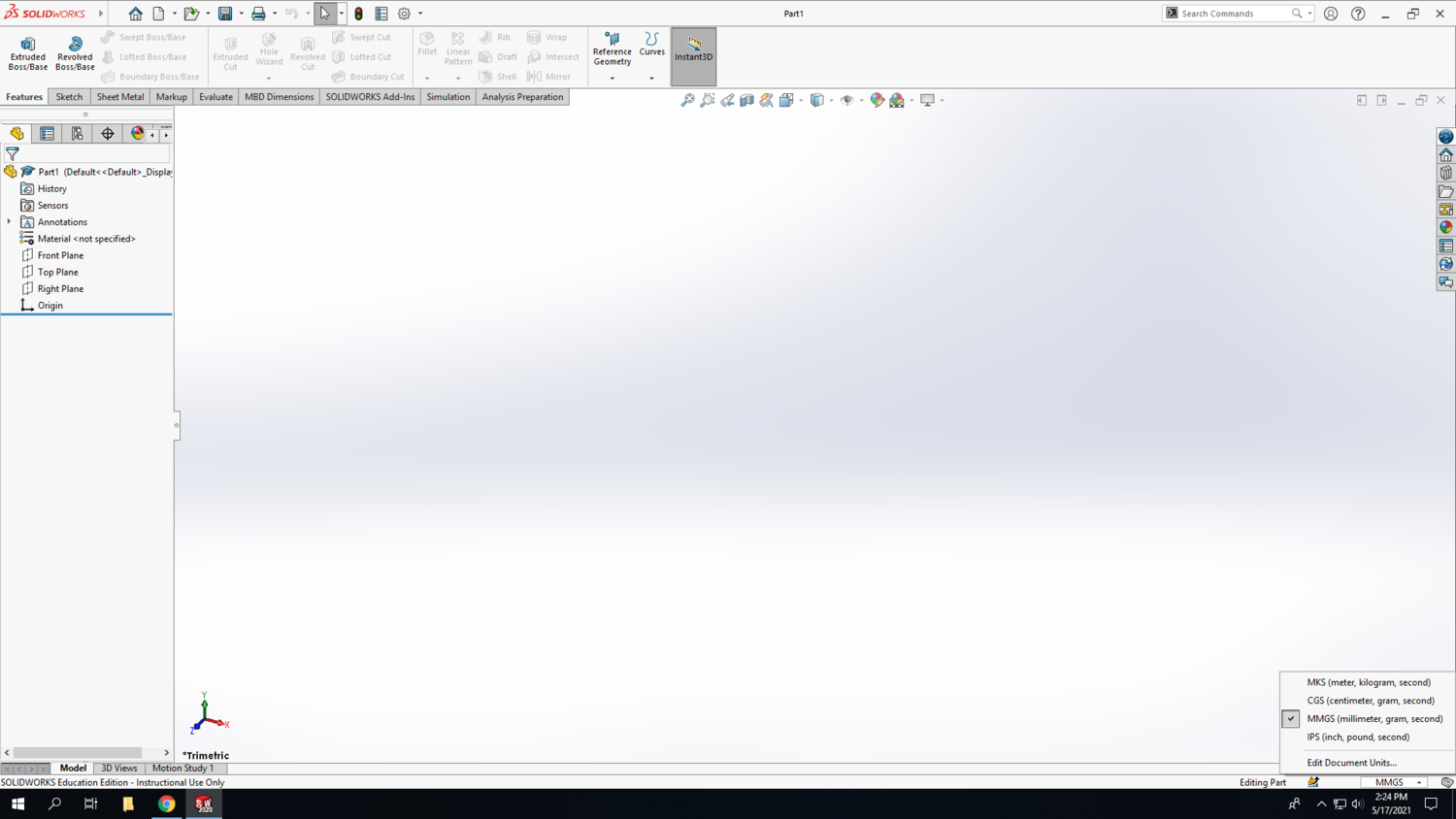
Step 1: Open SolidWorks, and select a new part. Don't forget to save your file frequently as you go. In the bottom-right corner of your Solidworks window, set the units to MMGS (millimeter, gram, second).
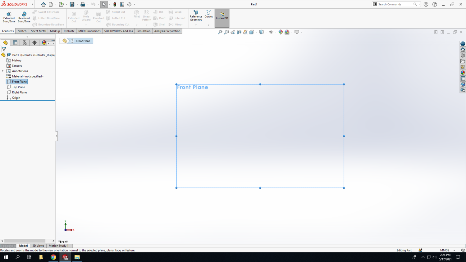
Step 2: Select the Front Plane in the design tree (the left column on your screen) to begin your sketch. Click on the Sketch tab above and click Sketch.
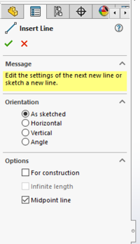
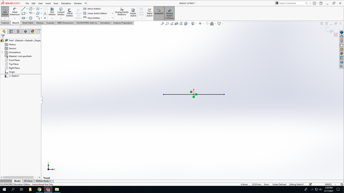
Step 3: The first line is going to be centered at the origin. After selecting the line command, check the “midpoint line” box in the left panel. Where you select will become the location of the center of the line. Select the origin and draw a horizontal line.
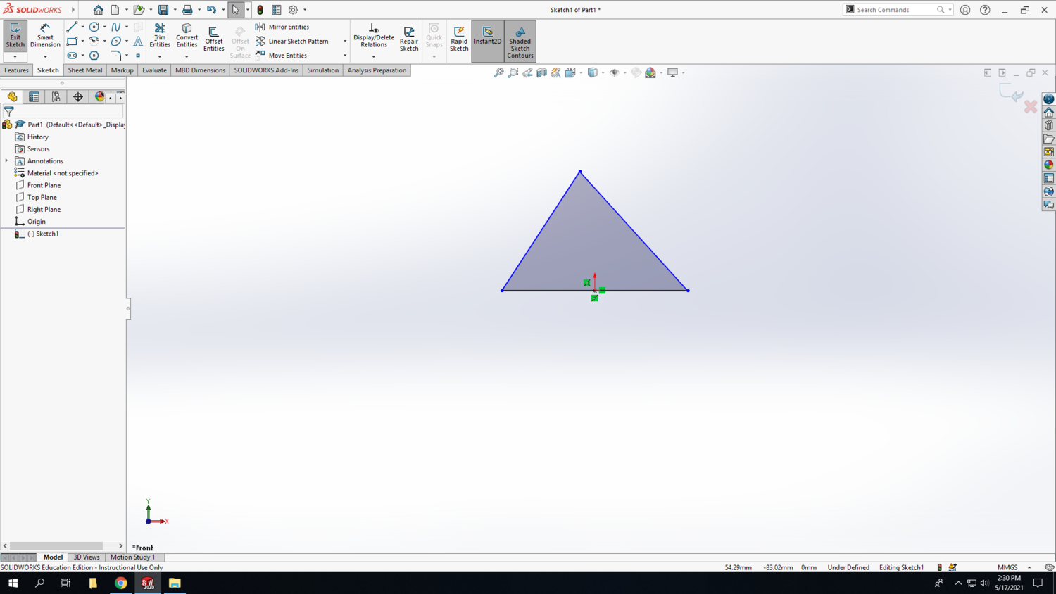
Insert another line beginning at the end point of our current line and complete the triangle. At this point, the sides do not need to be perfect, just the general shape is needed.
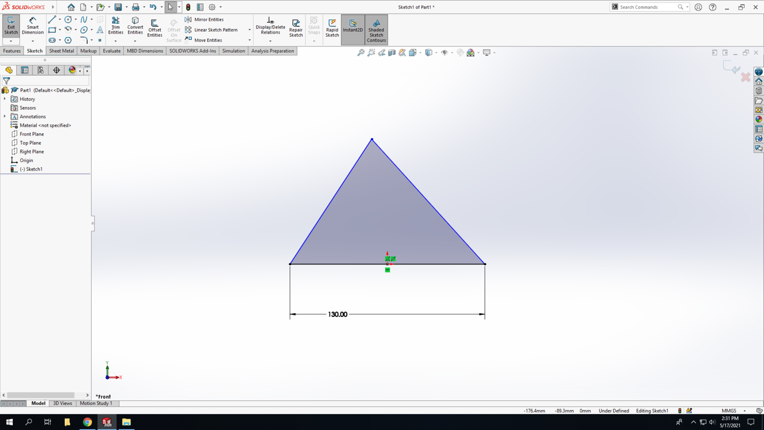
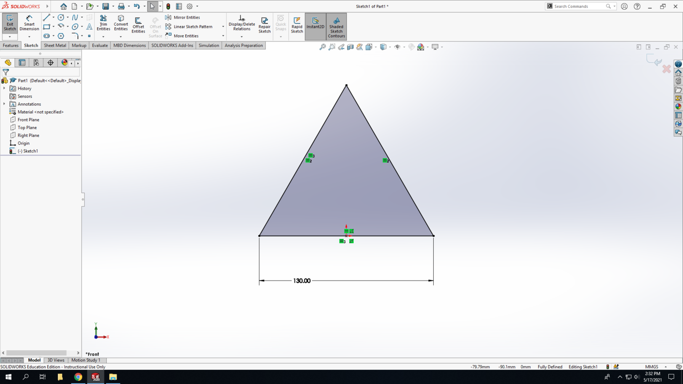
Step 4: Using the Smart dimension tool, make the bottom side of the triangle 130 mm.
Step 5: Next we are going to use a relation. A relation relates (who would’ve guessed it) or constrains a component of the sketch to another sketch entity to help define the sketch.
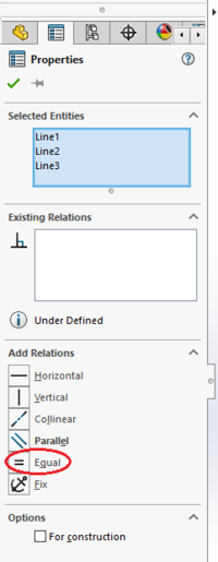
Ctrl + select all of the lines making up the triangle. In the left panel under the “Add Relations” section, select “equal.” This will make all of the lengths equal, giving us the equilateral triangle we are aiming for.
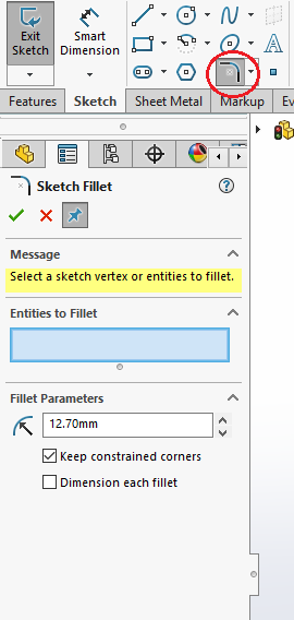
Step 6: A fillet will be used to achieve the rounded corners of our triangle. Select the “Sketch Fillet” command in the toolbar. This command creates a round corner between two lines. In the left panel, set the fillet parameter to have a radius of 12.7 mm (equivalent to our ½ die).
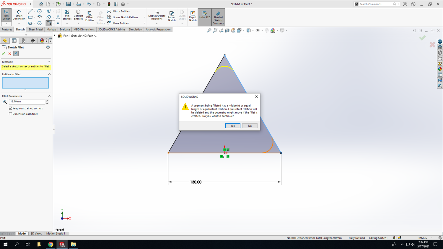
Select two adjacent sides of the triangle to create a round between them. Because of the relation we used, an alert will pop up; hit yes to continue and be sure to apply the fillet to each of the corners. Repeat this for each corner of the triangle.
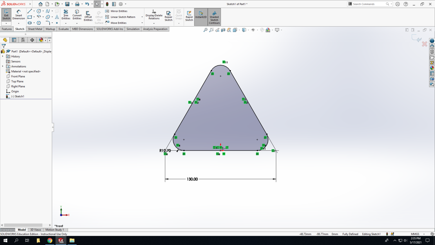
A yellow line will preview the fillet on the triangle; if these lines appear correct hit the green check mark to apply the fillets.
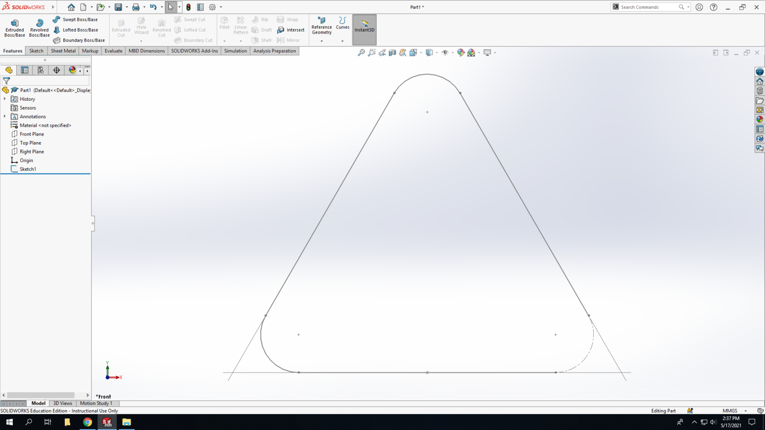
Step 7: The shape we are drawing is the guideline for the triangle. Since it needs an open corner, select one of the round edges and change it to a construction line. Exit the sketch. The shape should look like this:
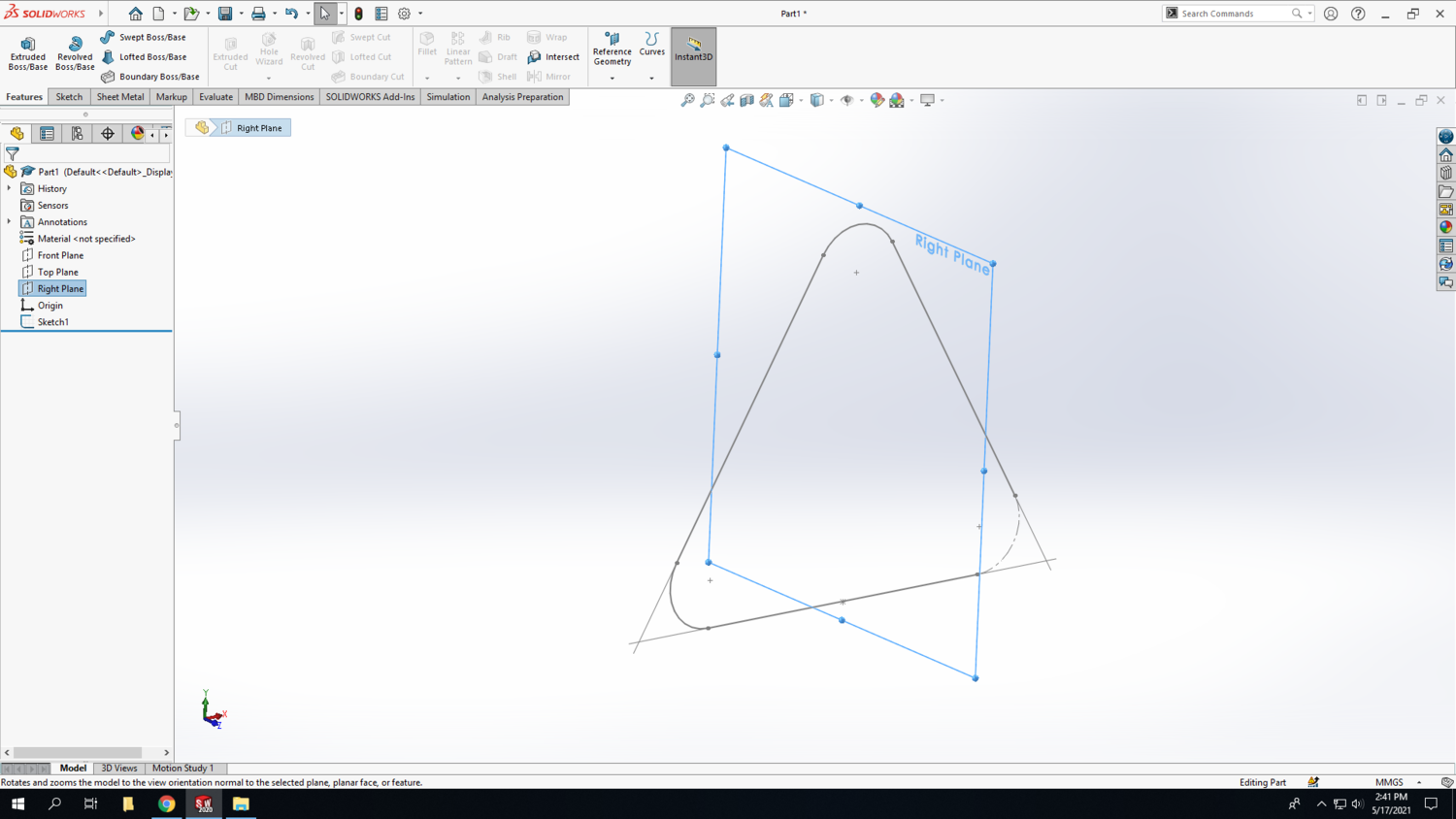
Step 8: Now we will be turning our lines into a 3D model. In the design tree, select the “Right Plane” and begin a new sketch
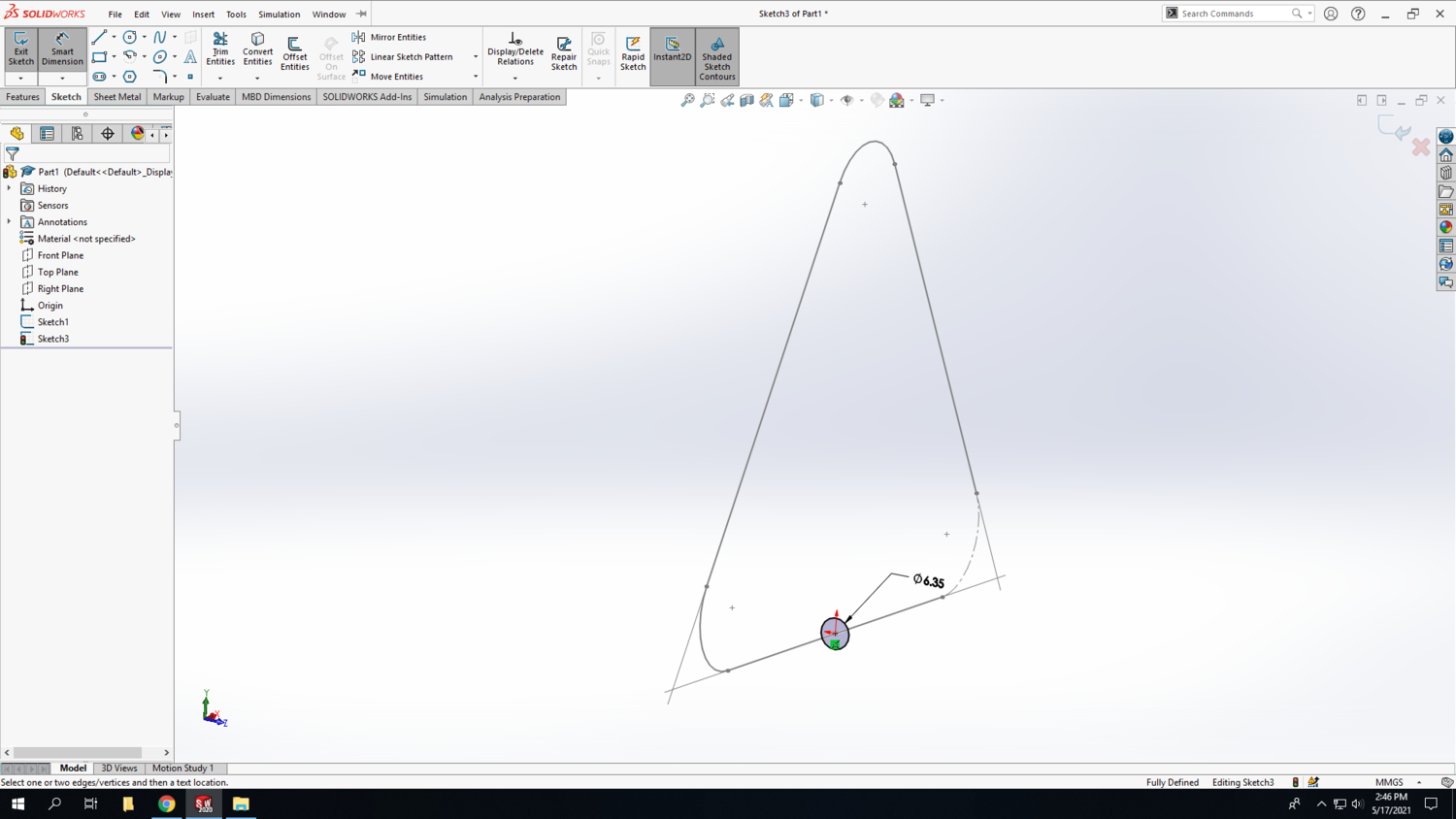
Step 9: Draw a circle with the center at the origin, also the midpoint of the baseline. The circle will be perpendicular to the current drawing. Use smart dimension to make it the same diameter as your material, here we are using ¼” brass tubing (6.35mm).
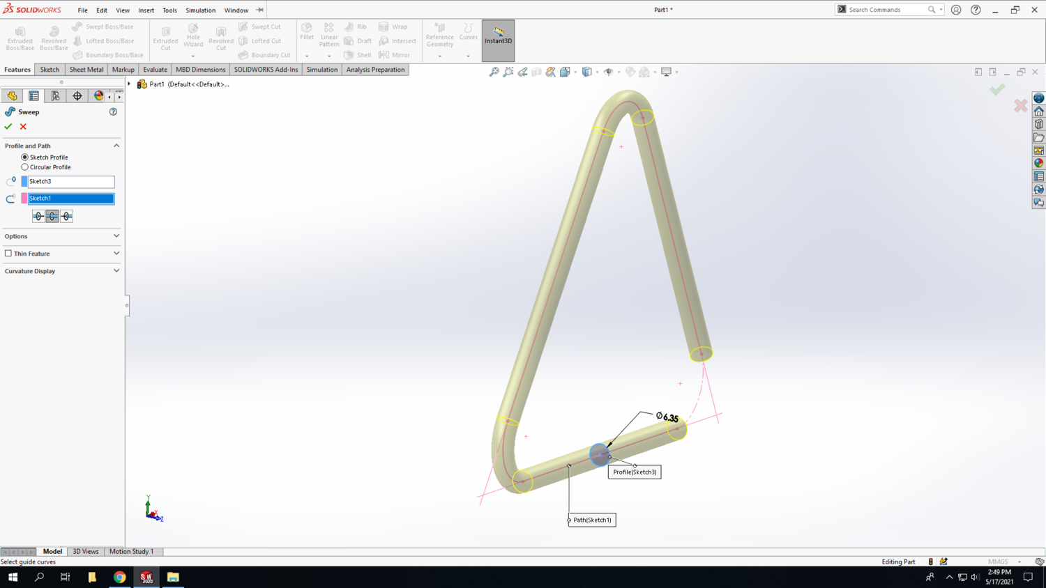
Step 10: Once the circle is drawn, go to the features tab and select “Swept Boss/Base.” This will extrude the selected contour along a specified path. The Sweep options will popup in the left panel. Click in the blue box and select the small circle we just created. Then click in the pink box and select the triangle as the path. Then select the bi-directional box below to extrude the circle the entire length of the triangle.
Hit the green check to create the 3D solid.
Hand Bender
Step 1:
Using a piece of metal rod and the hand bender, you will make your triangle. This TV uses ¼” brass stock.
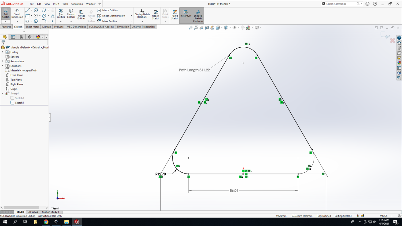
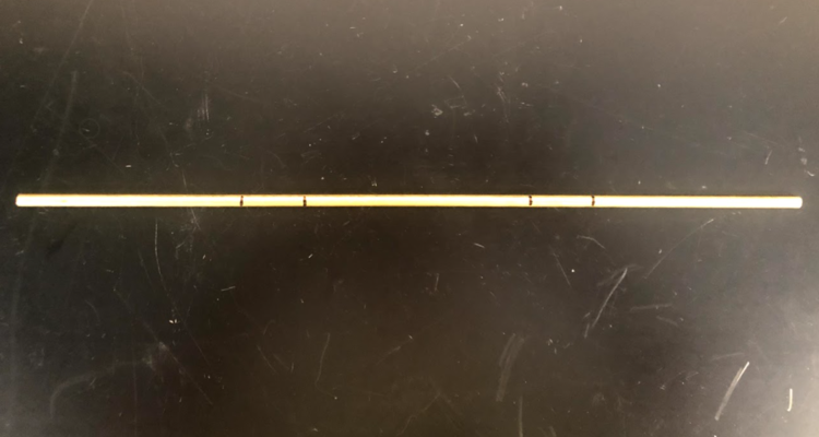
Begin with a piece about 312mm (12.25in) long. Mark 86 mm (3.4in) from one end. This will be the start point of the bend.
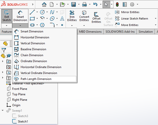
The full length of the triangle can be found in SolidWorks by adding a dimension to the sketch in which the triangle was drawn. Click the pop-out arrow under smart dimension to see more options, and then select “Path Length Dimension.”
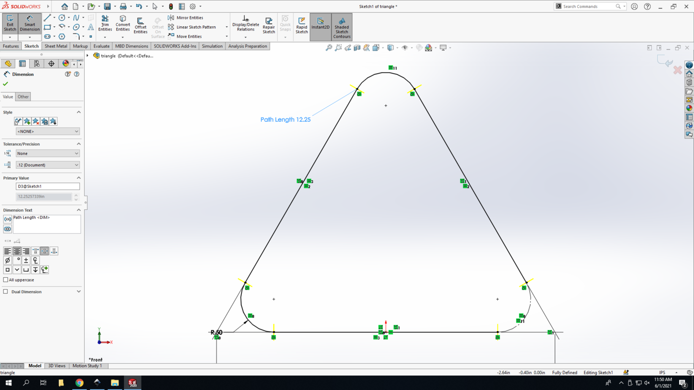
Select the triangle to apply the dimension. This will overdefine the sketch; since this is only a reference dimension, make it driven and select the green arrow. This tells you the measurement of the whole triangular path; this should be 12.25 inches.
Step 2:
The point of the bend is found using smart dimension again. Select the bottom line of the triangle to apply the dimension; again, leave the dimension driven.
Step 3:
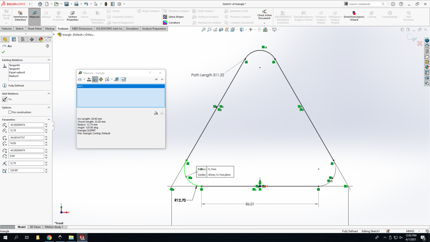
From that mark, measure 26.5 mm (~1in) and make another mark. This is the perimeter of the rounded corner. We will find this by using the “Measure” tool under the evaluate tab. Select the curve you want to measure, and the information will appear in the measure pop up box. Measure will give you a lot of information, but here we are just interested in the arc length.
[triangle_measure]
Step 4:
Repeat the same markings from the other end of the rod.
Step 5:
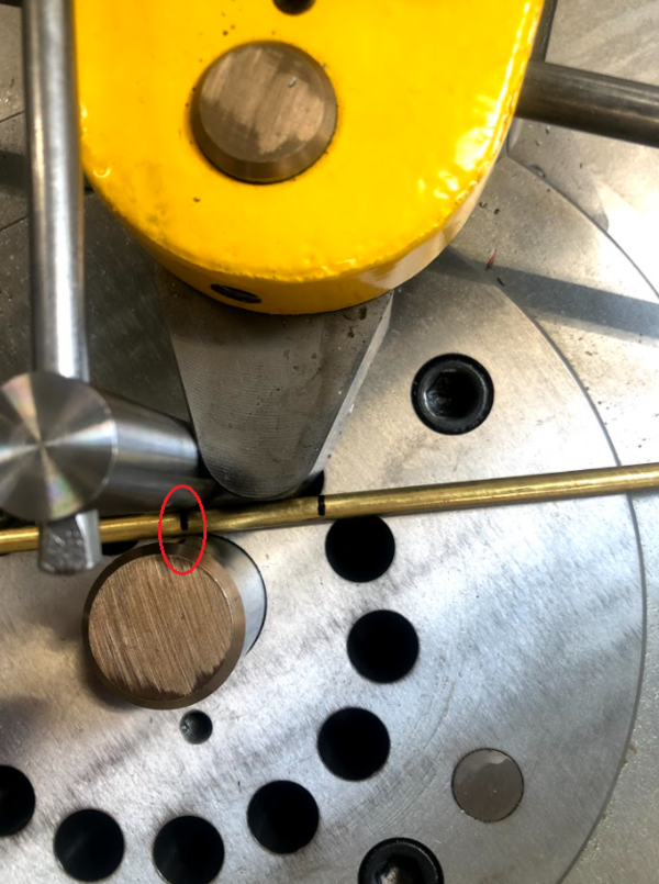
Moving on to the hand bender. The hand bender has two pins: the radius pin in the center that sets the radius of the bend, and the holding pin that holds the piece of metal against the radius pin.
You are going to position the rod so the first mark from the end is held between the radius and the holding pin. Make sure that the rod is held tightly between the pins.
Step 6:
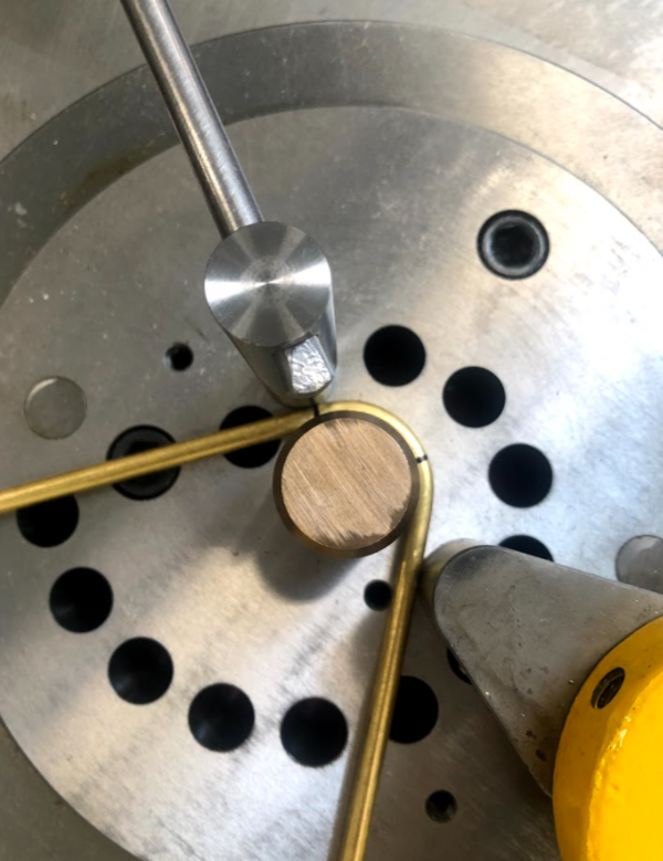
Pull the handle to bend the rod until the second mark touches the center pin. Then bend it a bit further because the metal has some spring so it will bounce back slightly.
Step 7:
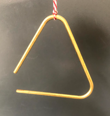
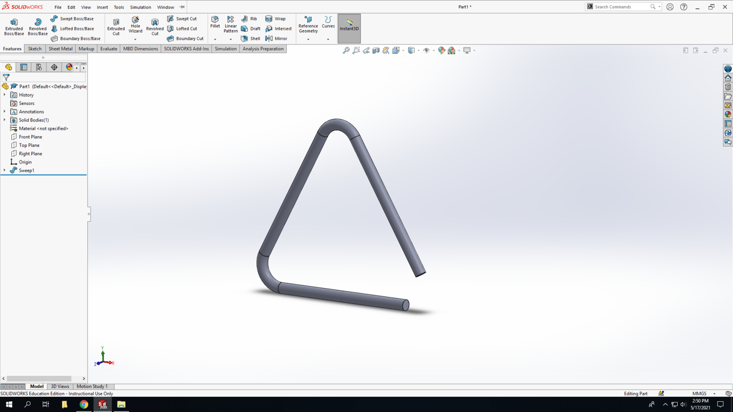
Repeat this using the marks on the other side. Tie a string to the top, and now you have a triangle! Call the family to dinner or go make some music!
