Difference between revisions of "Hydraulic Press"
| (62 intermediate revisions by 5 users not shown) | |||
| Line 1: | Line 1: | ||
{{#set: | {{#set: | ||
|Is equipment=True | |Is equipment=True | ||
| + | |Has name={{PAGENAME}} | ||
|Has make=Baileigh | |Has make=Baileigh | ||
|Has model=30T Air Press | |Has model=30T Air Press | ||
| − | |Has | + | |Has serial number=142263020 |
| + | |Has life expectancy= | ||
| + | |Has year of manufacture or purchase= | ||
| + | |Has replacement cost= | ||
|Is located in facility= Machine Shop | |Is located in facility= Machine Shop | ||
|Is used in domain=Metal | |Is used in domain=Metal | ||
|Has function=Shop Press | |Has function=Shop Press | ||
| + | |Has certification=https://georgefox.instructure.com/courses/1283 | ||
|Has url=http:https://www.baileigh.com/shop-press-hsp-30a | |Has url=http:https://www.baileigh.com/shop-press-hsp-30a | ||
|Has icon=File: Hydraulic_pressIcon.png | |Has icon=File: Hydraulic_pressIcon.png | ||
| Line 13: | Line 18: | ||
|Has imagedesc=Baileigh 30 Ton Hydraulic/Air Press | |Has imagedesc=Baileigh 30 Ton Hydraulic/Air Press | ||
|Has description=Baileigh 30 Ton Hydraulic/Air Press | |Has description=Baileigh 30 Ton Hydraulic/Air Press | ||
| − | |Has ace= | + | |Has ace=Needed;Makerhub@georgefox.edu |
}} | }} | ||
| − | [[{{#show: {{FULLPAGENAME}}|?Has icon|link=none}}| | + | [[{{#show: {{FULLPAGENAME}}|?Has icon|link=none}}|140px|left|top|{{#show: {{FULLPAGENAME}}|?Has icondesc}}]] |
[[{{#show: {{FULLPAGENAME}}|?Has image|link=none}}|300px|thumb|upright=1.5|{{#show: {{FULLPAGENAME}}|?Has imagedesc}}]] | [[{{#show: {{FULLPAGENAME}}|?Has image|link=none}}|300px|thumb|upright=1.5|{{#show: {{FULLPAGENAME}}|?Has imagedesc}}]] | ||
| Line 21: | Line 26: | ||
Model: {{#show: {{PAGENAME}} |?Has model}} | Model: {{#show: {{PAGENAME}} |?Has model}} | ||
| + | |||
| + | Serial Number: {{#show: {{PAGENAME}} |?Has serial number}} | ||
Ace: {{#show: {{PAGENAME}} |?Has ace.Has name}} ({{#show: {{PAGENAME}} |?Has ace.Has email address}}). | Ace: {{#show: {{PAGENAME}} |?Has ace.Has name}} ({{#show: {{PAGENAME}} |?Has ace.Has email address}}). | ||
| Line 33: | Line 40: | ||
A '''hydraulic press''' is a machine tool that uses a hydraulic cylinder to generate a compressive force. They are often used in shops to press interference fit parts together, such as gears onto shafts or bearings into housings. | A '''hydraulic press''' is a machine tool that uses a hydraulic cylinder to generate a compressive force. They are often used in shops to press interference fit parts together, such as gears onto shafts or bearings into housings. | ||
| − | Some of the other uses include bending and forming metal. Some presses use a manual pump to produce the force while others use compressed air or a | + | Some of the other uses include bending and forming metal. Some presses use a manual pump to produce the force while others use compressed air or a hydraulic pump driven by an electric motor. |
Here is an example of this piece of equipment being used. | Here is an example of this piece of equipment being used. | ||
| Line 48: | Line 55: | ||
*'''Ram'''- This is is the end of the hydraulic cylinder rod that moves and pushes against your work piece. | *'''Ram'''- This is is the end of the hydraulic cylinder rod that moves and pushes against your work piece. | ||
*'''Pump Handle Socket'''- This is the location for handle placement while pumping up the hydraulic system. | *'''Pump Handle Socket'''- This is the location for handle placement while pumping up the hydraulic system. | ||
| + | *'''Table Plates'''- Steel blocks used to support the work piece while using the press. | ||
| + | |||
| + | [[Media:Baileigh_Shop_Press.pdf|Hydraulic Press User Manual]] | ||
==Training== | ==Training== | ||
| − | ==== | + | ====Operation==== |
The press consists of a pump and hydraulic ram that moves down towards the table as the handle is cycled. The hydraulic press has a 58 mm diameter ram and can produce 30 tons of force. Some of the many uses including installation and removal of press fit parts as well as metal forming and punching. The ram can also be powered using compressed shop air, but should never be attempted without the shop techs supervision. The ram can be adjusted laterally as need to accommodate a specific part. As long as the ram keeps moving the force will remain fairly low. When the cylinder stops moving the hydraulic pressure in the system will start to build. As the force increases so does the risk. Pieces that are subjected to a high amount of force can shatter or explode. Make sure you are aware of what is happening and don't keep pumping on the handle and increasing the force without knowing what is occurring. | The press consists of a pump and hydraulic ram that moves down towards the table as the handle is cycled. The hydraulic press has a 58 mm diameter ram and can produce 30 tons of force. Some of the many uses including installation and removal of press fit parts as well as metal forming and punching. The ram can also be powered using compressed shop air, but should never be attempted without the shop techs supervision. The ram can be adjusted laterally as need to accommodate a specific part. As long as the ram keeps moving the force will remain fairly low. When the cylinder stops moving the hydraulic pressure in the system will start to build. As the force increases so does the risk. Pieces that are subjected to a high amount of force can shatter or explode. Make sure you are aware of what is happening and don't keep pumping on the handle and increasing the force without knowing what is occurring. | ||
| − | Make sure you have a full understanding of what you are attempting to accomplish before possibly getting into a risky situation. Ask a supervisor if you have any questions. Its important to properly set up the press before performing a job. It is good practice to observe the setup from various angles to ensure part alignment. If there is any risk something could fall on the floor during the process have a box or padding to catch the part. The table needs to be moved to the proper height to accommodate the work piece and ram travel. You want to avoid extending the ram farther than needed to prevent material from tipping over. Always make sure you will have enough ram travel to perform the task at hand. The release valve handle will need to be turned fully clockwise to allow the system to build pressure. It is imperative that you keep the work piece from tipping or slipping to the side while applying force to prevent flying parts and or damage. You should use a guide when pressing in a pin to prevent the pin or rod from slipping while installation. Keep an eye on the force gauge to verify your work piece is not sticking or hanging up. When the piece is pressed to its maximum travel pressure will start to build and could cause damage if you keep cycling the handle. Be aware that a part or piece could bottom out and avoid applying more force at the end of your parts travel than needed. | + | Make sure you have a full understanding of what you are attempting to accomplish before possibly getting into a risky situation. Ask a supervisor if you have any questions. Its important to properly set up the press before performing a job. It is good practice to observe the setup from various angles to ensure part alignment. If there is any risk something could fall on the floor during the process have a box or padding to catch the part. The table needs to be moved to the proper height to accommodate the work piece and ram travel. The table plates have two sides. One side is flat and the other has a V shape for holding round parts. The plates have a pin in each corner that prevent the plate from sliding off the table. You want to avoid extending the ram farther than needed to prevent material from tipping over. Always make sure you will have enough ram travel to perform the task at hand. The release valve handle will need to be turned fully clockwise to allow the system to build pressure. It is imperative that you keep the work piece from tipping or slipping to the side while applying force to prevent flying parts and or damage. You should use a guide when pressing in a pin to prevent the pin or rod from slipping while installation. Keep an eye on the force gauge to verify your work piece is not sticking or hanging up. When the piece is pressed to its maximum travel pressure will start to build and could cause damage if you keep cycling the handle. Be aware that a part or piece could bottom out and avoid applying more force at the end of your parts travel than needed. |
====Demonstration==== | ====Demonstration==== | ||
| − | Demonstrate you can setup the press and safety install a pin with a press fit. You will also press the pin out after insertion. The pin, plate, and | + | Demonstrate you can setup the press and safety install a pin with a press fit into an aluminum block. You will also press the pin out after insertion. The pin has an outer diameter of .375" and the block has 4 holes that have been reamed to .374" The dowel pin, plate, guide, and extraction tool will be provided. Remember the guide will help keep the pin straight during installation. The extraction tool has a pin with a smaller diameter that will assist in pressing out the dowel pin. You will also need an extra person to help adjust the table height. |
| − | <br> | + | <br><br> |
| − | + | Picture of tooling required:<br> | |
| + | |||
[[File:Hydraulic Press Demonstration.jpg|600px|thumb|none]] | [[File:Hydraulic Press Demonstration.jpg|600px|thumb|none]] | ||
| − | |||
| − | |||
| − | |||
| − | |||
| − | |||
| − | |||
| − | |||
| − | |||
| − | |||
| − | |||
| − | |||
| − | |||
| − | |||
| − | |||
| − | |||
| − | |||
| − | |||
| − | |||
| − | |||
| − | |||
====General Procedure==== | ====General Procedure==== | ||
| Line 92: | Line 83: | ||
1. Place the plate you will be pressing the pin into on the top of the table frame support blocks. | 1. Place the plate you will be pressing the pin into on the top of the table frame support blocks. | ||
| − | 2. Set the dowel pin into the guide and make sure the table frame and support plates are high enough for the ram to be within an inch of the top of the pin. | + | 2. Set the dowel pin into the guide and make sure the table frame and support plates are high enough for the ram to be within an inch of the top of the dowel pin. |
[[File:HP Step 1.jpg|none|thumb]] | [[File:HP Step 1.jpg|none|thumb]] | ||
| − | 3. If you need to adjust the table frame height remove the safety clips from the pins supporting the table | + | 3. If you need to adjust the table frame height remove the table plates and assembly pieces before removing the safety clips from the pins supporting the table. The table plates are heavy so be carefule not to drop them. |
| − | 4. To move the table frame down you will remove the two upper pins and reinstall them in the | + | 4. To move the table frame down you will remove the two upper table support pins and reinstall them in the desired holes below. |
| − | 5. You will need a second person to help lift the table frame slightly while removing the remaining two pins and slowly lower the table onto the pins below. | + | 5. You will need a second person to help lift the table frame slightly while removing the remaining two table support pins and slowly lower the table onto the support pins below. |
| − | 6. Reinstall the top two pins and safety clips. | + | 6. Reinstall the top two table support pins and safety clips. |
| − | 7. To move the table frame up you will leave the lower pins installed and remove the two upper pins. The lower pins will help prevent the table from accidentally dropping to the floor while making an adjustment. | + | 7. To move the table frame up you will leave the lower support pins installed and remove the two upper support pins. The lower support pins will help prevent the table from accidentally dropping to the floor while making an adjustment. |
| − | 8. You will need a second person to help lift the table frame while installing the two removed pins in the 2 lower positions. | + | 8. You will need a second person to help lift the table frame while installing the two removed support pins in the 2 lower positions. |
| − | 9. Install the 2 remaining top pins and safety clips. | + | 9. Install the 2 remaining top support pins and safety clips. |
10. Place table support plates and assembly pieces back onto the table. | 10. Place table support plates and assembly pieces back onto the table. | ||
| Line 121: | Line 112: | ||
14. Slowly pump the handle while watching the force gauge and the pin. Make sure pressure is not building. | 14. Slowly pump the handle while watching the force gauge and the pin. Make sure pressure is not building. | ||
| − | 15. If the pin starts at an angle do NOT continue to apply force as this | + | 15. If the pin starts at an angle do NOT continue to apply force as this could cause the dowel pin to slip sideways or damage the hole where the dowel presses into. |
| − | 16. When the pin is | + | 16. When the dowel pin is pressed to the bottom of the hole in the block it will contact the support plate and no longer be able to move. The bottoming out of the dowel pin will cause the force to increase on the gauge. Stop cycling the handle when the dowel pin reaches this point. |
| − | [[File:HP Step | + | [[File:HP Step 5.jpg|none|thumb]] |
| + | 17. Turn the pressure relief handle counterclockwise to retract the ram as needed. | ||
'''Pin Removal''' | '''Pin Removal''' | ||
| − | 1. Place the plate with the | + | 1. Place the plate with the pressed in dowel pin (facing downward) on top of the table support plates. You will need to leave a gap between the table plates for the pin to press though. |
[[File:HP Step 6.jpg|none|thumb]] | [[File:HP Step 6.jpg|none|thumb]] | ||
| − | 2. Check the distance between | + | 2. Check the distance between the pin extraction tool and the ram. If the gap is too large the ram will run out of travel before pressing out the dowel pin. |
[[File:HP Step 8.jpg|none|thumb]] | [[File:HP Step 8.jpg|none|thumb]] | ||
| − | 3. If you need to adjust the table frame height remove the safety clips from the pins supporting the table | + | 3. If you need to adjust the table frame height remove the safety clips from the frame support pins supporting the table. Remove everything from the table to prevent accidentally dropping items on your feet. |
| − | 4. To move the table frame down you will remove the two upper pins and reinstall them in the | + | 4. To move the table frame down you will remove the two upper support pins and reinstall them in the desired holes below. |
| − | 5. You will need a second person to help lift the table frame slightly while removing the remaining two pins and slowly lower the table onto the pins below. | + | 5. You will need a second person to help lift the table frame slightly while removing the remaining two support pins and slowly lower the table onto the support pins below. |
| − | 6. Reinstall the top two pins and safety clips. | + | 6. Reinstall the top two support pins and safety clips. |
| − | 7. To move the table frame up you will leave the lower pins installed and remove the two upper pins. The lower pins will help prevent the table from accidentally dropping to the floor while making an adjustment. | + | 7. To move the table frame up you will leave the lower support pins installed and remove the two upper support pins. The lower support pins will help prevent the table from accidentally dropping to the floor while making an adjustment. |
| − | 8. You will need a second person to help lift the table frame while installing the two removed pins in the 2 lower positions. | + | 8. You will need a second person to help lift the table frame while installing the two removed support pins in the 2 lower positions. |
| − | 9. Install the 2 remaining top pins and safety clips. | + | 9. Install the 2 remaining top support pins and safety clips. |
10. Place table support plates and assembly pieces back onto the table. | 10. Place table support plates and assembly pieces back onto the table. | ||
| Line 154: | Line 146: | ||
11. Make sure the pressure relief handle has been turned clockwise to allow pressure to build. | 11. Make sure the pressure relief handle has been turned clockwise to allow pressure to build. | ||
| − | 12. Insert the pump handle into the handle socket. | + | 12. Insert the pump handle into the handle socket. |
| + | |||
| + | 13. Center the extraction tool with the end of the dowel pin to be removed. | ||
| − | 13. Slowly cycle the handle while watching the force gauge and the pin. Make sure the pin is starting to move. | + | 13. Slowly cycle the handle while watching the force gauge and the dowel pin. Make sure the pin is starting to move. |
| − | [[File:HP Step | + | [[File:HP Step 9.jpg|none|thumb]] |
| − | 14. You will continue to press the pin using the extraction tool | + | 14. You will continue to press the pin using the extraction tool. |
15. As the dowel pin approaches the bottom of plate get ready to catch it to prevent it from falling on the floor. | 15. As the dowel pin approaches the bottom of plate get ready to catch it to prevent it from falling on the floor. | ||
| + | |||
| + | [[File:HP Step 10.jpg|none|thumb]] | ||
16. Turn the pressure relief handle counterclockwise to retract the ram. | 16. Turn the pressure relief handle counterclockwise to retract the ram. | ||
| Line 169: | Line 165: | ||
==Safety== | ==Safety== | ||
| − | When operating a hydraulic press be aware that extremely dangerous forces can be produced which could cause parts to shatter and fly like mini bullets. It's very important to keep an eye on the force gauge while increasing force and to be aware of the dangers of flying parts. Always keep you hands away from the ram and parts being pressed. Keep stacked parts as short as possible to prevent tilting or buckling. If you have questions ask a supervisor prior to attempting a project that could be potentially dangerous. Be aware that you may be working with heavy material located several feet above the floor and there is potential to drop metal on your feet. | + | When operating a hydraulic press be aware that extremely dangerous forces can be produced which could cause parts to shatter and fly like mini bullets. It's very important to keep an eye on the force gauge while increasing force and to be aware of the dangers of flying parts. Always keep you hands away from the ram and parts being pressed. Keep stacked parts as short as possible to prevent tilting or buckling. If you have questions ask a supervisor prior to attempting a project that could be potentially dangerous. Be aware that you may be working with heavy material located several feet above the floor and there is potential to drop metal on your feet. Make sure the 4 locking pins located on the table plates are engaged to prevent the plates from sliding off the table. |
==Certification== | ==Certification== | ||
| + | Complete the <strong>Machine Shop - {{PAGENAME}} Module</strong> at the link below to gain access to the {{PAGENAME}}. The Maker Hub Canvas course pertains to all facilities and equipment contained in the Maker Hub; simply complete the quizzes for the facilities/equipment you wish to use in the Maker Hub. Please email <span style="color:blue">makerhub@georgefox.edu</span> if you have any questions. | ||
| − | + | [https://georgefox.instructure.com/enroll/R6RF69 Maker Hub Canvas Course] | |
==Troubleshooting== | ==Troubleshooting== | ||
| Line 189: | Line 186: | ||
!Done By | !Done By | ||
|- | |- | ||
| − | | | + | |Wipe down |
| − | | | + | |As needed |
| − | | | + | |Student |
|} | |} | ||
Latest revision as of 14:46, 15 July 2025
Make: Baileigh
Model: 30T Air Press
Serial Number: 142263020
Ace: Needed (Makerhub@georgefox.edu).
Location: Machine Shop
Description
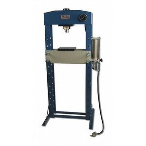
A hydraulic press is a machine tool that uses a hydraulic cylinder to generate a compressive force. They are often used in shops to press interference fit parts together, such as gears onto shafts or bearings into housings. Some of the other uses include bending and forming metal. Some presses use a manual pump to produce the force while others use compressed air or a hydraulic pump driven by an electric motor.
Here is an example of this piece of equipment being used.
Documentation
Terminology
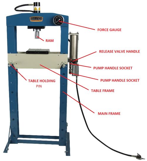
- Pressure Gauge- An indicator that uses a needle to indicate the amount of force being applied to the work piece.
- Release Valve Handle- This is the control handle for releasing the hydraulic pressure in the system. Turn the handle clockwise prior to charging the hydraulic system and counter-clockwise when releasing pressure.
- Table Holding Pin- 4 removable pins support the table and allow for height adjustment.
- Ram- This is is the end of the hydraulic cylinder rod that moves and pushes against your work piece.
- Pump Handle Socket- This is the location for handle placement while pumping up the hydraulic system.
- Table Plates- Steel blocks used to support the work piece while using the press.
Training
Operation
The press consists of a pump and hydraulic ram that moves down towards the table as the handle is cycled. The hydraulic press has a 58 mm diameter ram and can produce 30 tons of force. Some of the many uses including installation and removal of press fit parts as well as metal forming and punching. The ram can also be powered using compressed shop air, but should never be attempted without the shop techs supervision. The ram can be adjusted laterally as need to accommodate a specific part. As long as the ram keeps moving the force will remain fairly low. When the cylinder stops moving the hydraulic pressure in the system will start to build. As the force increases so does the risk. Pieces that are subjected to a high amount of force can shatter or explode. Make sure you are aware of what is happening and don't keep pumping on the handle and increasing the force without knowing what is occurring.
Make sure you have a full understanding of what you are attempting to accomplish before possibly getting into a risky situation. Ask a supervisor if you have any questions. Its important to properly set up the press before performing a job. It is good practice to observe the setup from various angles to ensure part alignment. If there is any risk something could fall on the floor during the process have a box or padding to catch the part. The table needs to be moved to the proper height to accommodate the work piece and ram travel. The table plates have two sides. One side is flat and the other has a V shape for holding round parts. The plates have a pin in each corner that prevent the plate from sliding off the table. You want to avoid extending the ram farther than needed to prevent material from tipping over. Always make sure you will have enough ram travel to perform the task at hand. The release valve handle will need to be turned fully clockwise to allow the system to build pressure. It is imperative that you keep the work piece from tipping or slipping to the side while applying force to prevent flying parts and or damage. You should use a guide when pressing in a pin to prevent the pin or rod from slipping while installation. Keep an eye on the force gauge to verify your work piece is not sticking or hanging up. When the piece is pressed to its maximum travel pressure will start to build and could cause damage if you keep cycling the handle. Be aware that a part or piece could bottom out and avoid applying more force at the end of your parts travel than needed.
Demonstration
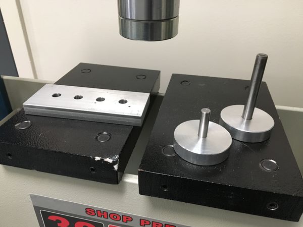
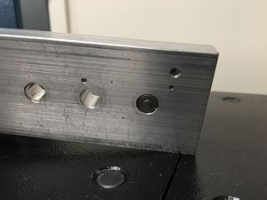
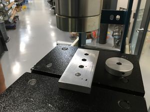
Demonstrate you can setup the press and safety install a pin with a press fit into an aluminum block. You will also press the pin out after insertion. The pin has an outer diameter of .375" and the block has 4 holes that have been reamed to .374" The dowel pin, plate, guide, and extraction tool will be provided. Remember the guide will help keep the pin straight during installation. The extraction tool has a pin with a smaller diameter that will assist in pressing out the dowel pin. You will also need an extra person to help adjust the table height.
Picture of tooling required:
General Procedure
Pin Insertion
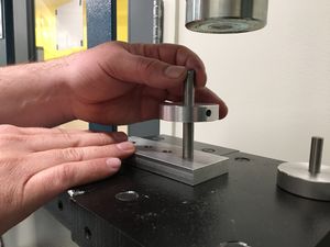
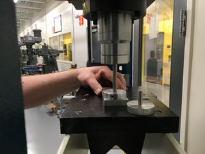
1. Place the plate you will be pressing the pin into on the top of the table frame support blocks.
2. Set the dowel pin into the guide and make sure the table frame and support plates are high enough for the ram to be within an inch of the top of the dowel pin.
3. If you need to adjust the table frame height remove the table plates and assembly pieces before removing the safety clips from the pins supporting the table. The table plates are heavy so be carefule not to drop them.
4. To move the table frame down you will remove the two upper table support pins and reinstall them in the desired holes below.
5. You will need a second person to help lift the table frame slightly while removing the remaining two table support pins and slowly lower the table onto the support pins below.
6. Reinstall the top two table support pins and safety clips.
7. To move the table frame up you will leave the lower support pins installed and remove the two upper support pins. The lower support pins will help prevent the table from accidentally dropping to the floor while making an adjustment.
8. You will need a second person to help lift the table frame while installing the two removed support pins in the 2 lower positions.
9. Install the 2 remaining top support pins and safety clips.
10. Place table support plates and assembly pieces back onto the table.
11. Place the dowel pin into the guide and align the pin with the hole in the plate. Its good practice to keep the dowel pin centered on the ram so the force is centered.
12. Make sure the pressure relief handle has been turned clockwise to allow pressure to build.
13. Insert the pump handle into the handle socket.
14. Slowly pump the handle while watching the force gauge and the pin. Make sure pressure is not building.
15. If the pin starts at an angle do NOT continue to apply force as this could cause the dowel pin to slip sideways or damage the hole where the dowel presses into.
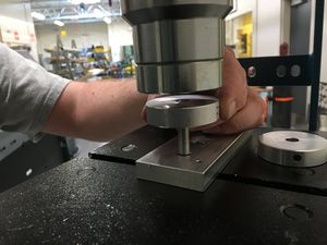
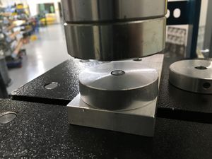
16. When the dowel pin is pressed to the bottom of the hole in the block it will contact the support plate and no longer be able to move. The bottoming out of the dowel pin will cause the force to increase on the gauge. Stop cycling the handle when the dowel pin reaches this point.
17. Turn the pressure relief handle counterclockwise to retract the ram as needed.
Pin Removal
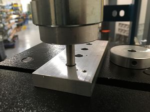
1. Place the plate with the pressed in dowel pin (facing downward) on top of the table support plates. You will need to leave a gap between the table plates for the pin to press though.
2. Check the distance between the pin extraction tool and the ram. If the gap is too large the ram will run out of travel before pressing out the dowel pin.
3. If you need to adjust the table frame height remove the safety clips from the frame support pins supporting the table. Remove everything from the table to prevent accidentally dropping items on your feet.
4. To move the table frame down you will remove the two upper support pins and reinstall them in the desired holes below.
5. You will need a second person to help lift the table frame slightly while removing the remaining two support pins and slowly lower the table onto the support pins below.
6. Reinstall the top two support pins and safety clips.
7. To move the table frame up you will leave the lower support pins installed and remove the two upper support pins. The lower support pins will help prevent the table from accidentally dropping to the floor while making an adjustment.
8. You will need a second person to help lift the table frame while installing the two removed support pins in the 2 lower positions.
9. Install the 2 remaining top support pins and safety clips.
10. Place table support plates and assembly pieces back onto the table.
11. Make sure the pressure relief handle has been turned clockwise to allow pressure to build.
12. Insert the pump handle into the handle socket.
13. Center the extraction tool with the end of the dowel pin to be removed.
13. Slowly cycle the handle while watching the force gauge and the dowel pin. Make sure the pin is starting to move.
14. You will continue to press the pin using the extraction tool.
15. As the dowel pin approaches the bottom of plate get ready to catch it to prevent it from falling on the floor.
16. Turn the pressure relief handle counterclockwise to retract the ram.
17. Reset the space.
Safety
When operating a hydraulic press be aware that extremely dangerous forces can be produced which could cause parts to shatter and fly like mini bullets. It's very important to keep an eye on the force gauge while increasing force and to be aware of the dangers of flying parts. Always keep you hands away from the ram and parts being pressed. Keep stacked parts as short as possible to prevent tilting or buckling. If you have questions ask a supervisor prior to attempting a project that could be potentially dangerous. Be aware that you may be working with heavy material located several feet above the floor and there is potential to drop metal on your feet. Make sure the 4 locking pins located on the table plates are engaged to prevent the plates from sliding off the table.
Certification
Complete the Machine Shop - Hydraulic Press Module at the link below to gain access to the Hydraulic Press. The Maker Hub Canvas course pertains to all facilities and equipment contained in the Maker Hub; simply complete the quizzes for the facilities/equipment you wish to use in the Maker Hub. Please email makerhub@georgefox.edu if you have any questions.
Troubleshooting
If you pump the handle and the ram doesn't move try tightening the release valve knob.
Maintenance
General maintenance
Keep the press clean. The hydraulic oil level and hoses should be checked by the tech on a regular basis. If you notice any hydraulic leaks notify the technician.
Specific Maintenance Tasks
| Maintenance Procedure | Frequency | Done By |
|---|---|---|
| Wipe down | As needed | Student |
