Difference between revisions of "Dimension 3D Printer"
| (4 intermediate revisions by 4 users not shown) | |||
| Line 1: | Line 1: | ||
{{#set: | {{#set: | ||
| − | |Is equipment= | + | |Is equipment=False |
| − | |Is located in facility= | + | |Is located in facility= None |
| − | |Is used in domain= | + | |Is used in domain=None |
|Has name={{PAGENAME}} | |Has name={{PAGENAME}} | ||
|Has icon=File:dimension_printer_icon.png | |Has icon=File:dimension_printer_icon.png | ||
| Line 18: | Line 18: | ||
[[{{#show: {{FULLPAGENAME}}|?Has icon|link=none}}|100px|left|top|{{#show: {{FULLPAGENAME}}|?Has icondesc}}]] | [[{{#show: {{FULLPAGENAME}}|?Has icon|link=none}}|100px|left|top|{{#show: {{FULLPAGENAME}}|?Has icondesc}}]] | ||
[[{{#show: {{FULLPAGENAME}}|?Has image|link=none}}|thumb|300px|upright=1.5|{{#show: {{FULLPAGENAME}}|?Has imagedesc}}]] | [[{{#show: {{FULLPAGENAME}}|?Has image|link=none}}|thumb|300px|upright=1.5|{{#show: {{FULLPAGENAME}}|?Has imagedesc}}]] | ||
| + | |||
| + | Make: {{#show: {{PAGENAME}} |?Has make}} | ||
Model: {{#show: {{PAGENAME}} |?Has model}} | Model: {{#show: {{PAGENAME}} |?Has model}} | ||
| Line 90: | Line 92: | ||
==Certification== | ==Certification== | ||
| − | + | Canvas Quiz | |
==Troubleshooting== | ==Troubleshooting== | ||
Latest revision as of 14:53, 11 February 2022
<ul><li>"None" is not in the list (Computer Lab, Finishing Room, Machine Shop, Meeting Rooms, PCB Lab, Prototype Lab, The Hub, The Vault, Tool Room, Welding Shop, ...) of allowed values for the "Is located in facility" property.</li> <!--br--><li>"None" is not in the list (Cloth, Crafts, Electronics, Leather, Metal, Painting, Plastic, Vinyl, Wood) of allowed values for the "Is used in domain" property.</li></ul>
Make: Stratasys
Model: 1200 SST
Ace: Joshua Consenz (jconsenz18@georgefox.edu).
Location:
Description
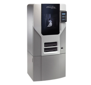
The Dimension is an FDM printer made by Stratasys. It is designed with ultimate simplicity in mind. The system enables you to build parts quickly, even if you’ve never used a 3D printer before. Its display panel prompts you to press a few keys to get you modeling quickly. The system models with ABS plastic, so modeled parts are strong and durable. ABS also ensures you’ll be able to drill, tap, sand, and paint your creations. With the speed and convenience of Breakaway Support Technology (BST) or Soluble Support Technology (SST), your completed parts are quickly available for review and test. SST allows for parts that are printed on the Dimension to have a more porous or odd geometry, such as overhangs, to be printed with relative ease in comparison with other filament based 3D printers.
Here is an example of this piece of equipment being used.
Insert video media here.
Documentation
Terminology
Insert terminology here
Training
Overview
Insert Text
Demonstration
Insert text
General Procedure
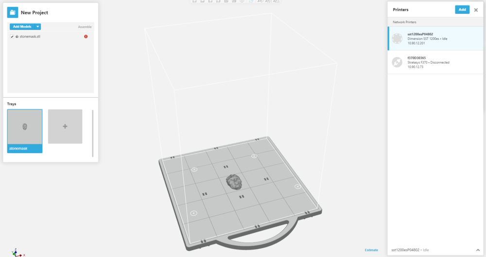
GrabCAD Print GrabCAD Print is the software that both the Dimension and F370 use, and allows you to easily orient and view the part you want to model. Both printers are web based, which allows you to start the print from the one of the lab's computers.
On Opening GrabCAD, make sure that you select the printer you want to use for the part you want to print, the volunteers in the lab can help you determine which printer would work best. The menu the the right of the image shows the printer options, make sure you select the correct printer, in this case it is the Dimension. After ensuring you have the software correctly set up, open your file and place it on the build plate, Note: your file has to be in STL format to work with any printing software. The build plate is correctly scaled to the actual build plate, so when sizing up or down you can check the size and placement of the print with the build plate. Note: The following pictures show a single part being printed, during regular lab hours the Dimension is only started when the plate is mostly full to be printed overnight.
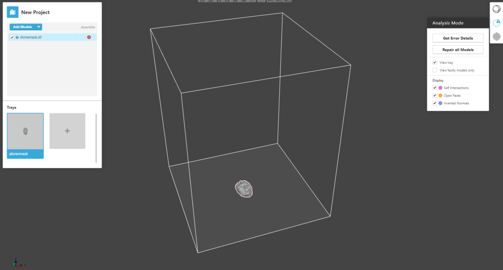
After importing all parts resize and orient your parts based on what the final product needs to be accomplished, with no one dimension being larger than 11 inches. Orienting the part is crucial for the print as this will determine how much support material is used as well as the strength of the part. To reduce support material used, orient your part with the most amount of surface are in contact with the plate, and with as few features positioned above cavities in the part. For maximum strength, orient your part so that the layers are parallel with the direction that the anticipated force will be applied, printing the layers perpendicular to the force can cause the layers to peel away from one another if the force is strong enough. If you have a red error in the model, enter analysis mode and click repair as shown in the picture below.
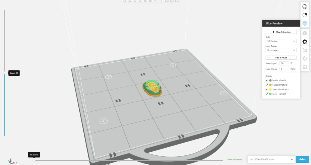
After correctly orienting and sizing the part, click Slice Preview to see how the Dimension will print your part, total layers, and path of the nozzle. Inspect your part to ensure that it will print correctly, and has a low chance of failing. You can watch an animation of your part being built, layer by layer, and do other analysis before printing. Click View Estimates, found in green near the bottom right corner, to see an approximation of how long the print will take, and the amount of material used. Be sure that this information is recorded in the Job Log. Fix any potential problems that you may have seen, and when you are sure that the part is correctly oriented on the build plate. You may now click Print, locate on the bottom right of the screen. Note: Very rarely will a single part be printed on the Dimension or F370, do not start a print without other parts unless cleared by the lab helper.
Printing
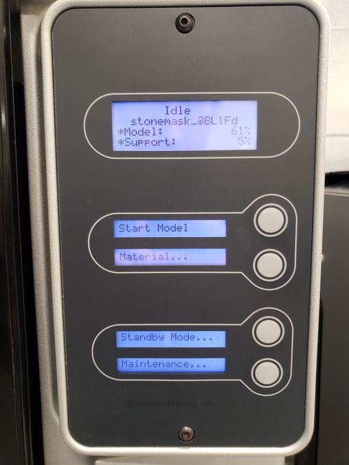
Once the Job has been sent to the Dimension, the control panel will display the most recent job sent to it. Check that the amount of support and model material, indicated on the top most display, is sufficient for the print and when ready, press the button to the right of the display that says start model.
Finished Parts
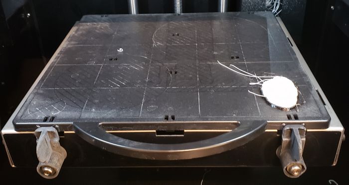
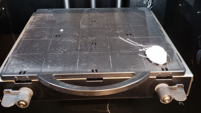
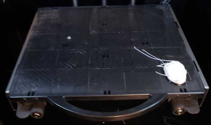
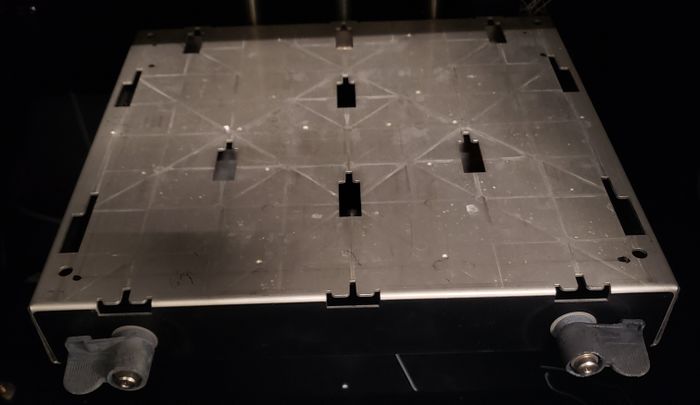
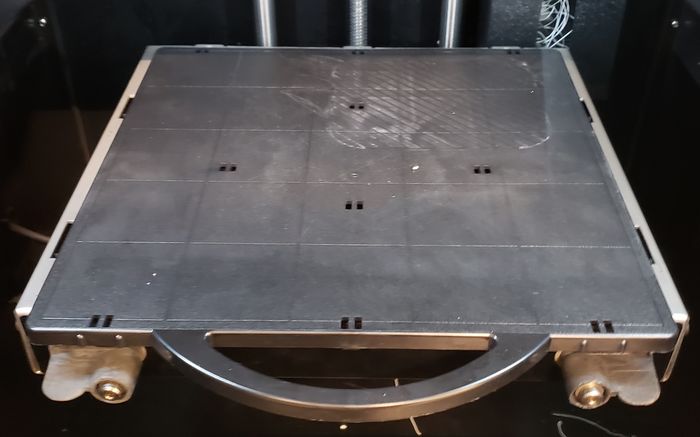
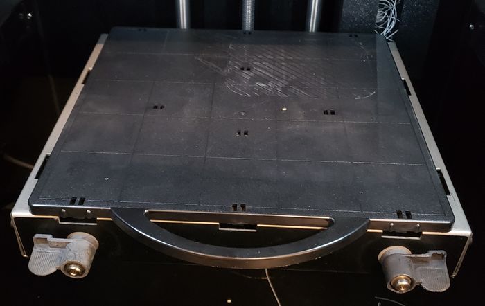
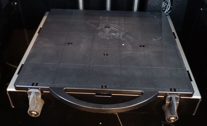
Once your part is finished, the plate can be removed by moving the tabs downward, pulling the plate forward, and lifting to remove. The following pictures show that process.
Removing Support Material
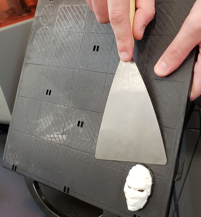
After removing the plate from the Dimension remove your part from the build plate by using the scraping tool and running the tool along the build plate, as shown in the picture below, and hitting the support material. Continue this process until the part is chipped off of the build plate. Once the part is removed, place in the Dissolvable Support Bath to remove any left over support material.
Safety
Insert text
Certification
Canvas Quiz
Troubleshooting
Maintenance
General maintenance
Changing Material
*Only volunteers will change out materials. If the Dimension runs out of filament or you would like to use a different color, please speak to a lab volunteer.*
The Dimension has two separate types of material, Model and Support. These two filaments are located on the front of the Dimension, with the Model in the top slot, and the support on the bottom. To change material for either modeling or support, click the button next to the display that says "Material . . ." and then click "Unload" from there. Select which filament you want to exchange, and then press in on that cartridge to remove it. The cartridge will click out, and you can now reel in the material as the Dimension removes it by spinning a wheel on the right hand side.
To load a material is very similar. Select the filament you want to replace, and insert the tip into a hole located in the slot. The Dimension will grab the filament and pull it up to the extruder nozzle. Place the cartridge back into the Dimension, and push it forwards until you hear a click.
Make: Stratasys
Specific Maintenance Tasks
| Maintenance Procedure | Frequency | Done By |
|---|---|---|
| Sample | Sample | Sample |
