Difference between revisions of "Slide Whistle"
| (2 intermediate revisions by the same user not shown) | |||
| Line 2: | Line 2: | ||
|Is tv=True | |Is tv=True | ||
|Has name={{PAGENAME}} | |Has name={{PAGENAME}} | ||
| − | |Has icon=File: | + | |Has icon=File:Slide_cad_27.png |
| − | |Has icondesc= | + | |Has icondesc=Slide Whistle Icon |
| − | |Has image=File: | + | |Has image=File:Slide_cad_27.png |
| − | |Has description= | + | |Has description=Slide Whistle |
| − | |||
| − | |||
|Uses software=Solidworks | |Uses software=Solidworks | ||
| Line 67: | Line 65: | ||
[[Image:slide_cad_7.png|250px]] | [[Image:slide_cad_7.png|250px]] | ||
[[Image:slide_cad_8.png|200px]] | [[Image:slide_cad_8.png|200px]] | ||
| − | [[Image:slide_cad_9.png| | + | [[Image:slide_cad_9.png|450px]] |
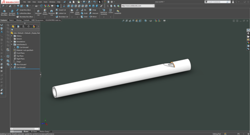
The pipe should now be white, just like real PVC! | The pipe should now be white, just like real PVC! | ||
Latest revision as of 15:08, 11 June 2021
In this TV, we will be creating a slide whistle.
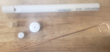
Bill of Materials
- ½” PVC
- ½” PVC cap with hole in end
- ½” dowel
- ½” delrin plug
- Welding rod
CAD
The body of the whistle is made from ½ inch schedule 40 PVC pipe.
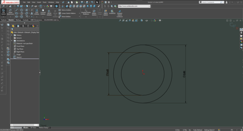
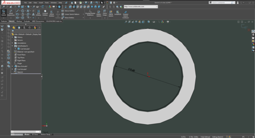
To model this, first create a sketch on the front plane. In this sketch, draw 2 circles. The outer diameter of the pipe is 0.85”, and the inner diameter is 0.62”. Make sure the circles are centered on the origin.
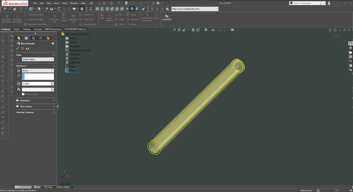
Then, extrude the profile to create the pipe. A length of 10.5 inches works well.
Next up, we need to create the notch that allows the whistle to produce sound. Start a new sketch on the right plane. In order to see the plane face on, hit space, and click the side of the cube that is parallel to the sketch.
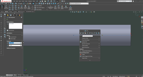
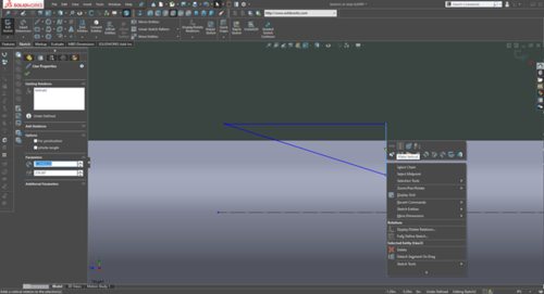
On this plane, first draw a line from the origin back into the pipe. Right click on it and set it to be construction geometry. This means that Solidworks will ignore the line when making the cut; but we can still measure off of it.
Next, draw a triangle using the line tool. The top line should be horizontal, and the vertical line should be, well, vertical.
Lock these lines to being horizontal and vertical by right clicking on them, and clicking either make horizontal or make vertical.
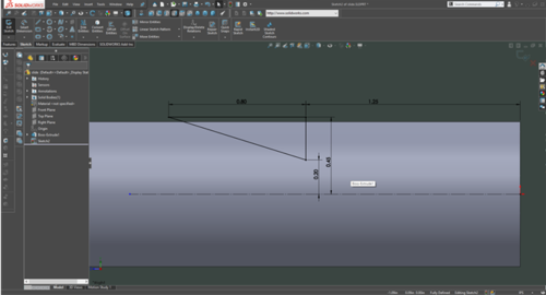
Next, insert dimensions to define the location and size of the cut. It should be 1.25” from the beginning of the pipe, and 0.2” from the center line.
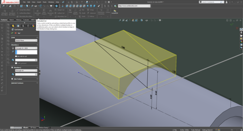
Once all dimensions are inserted, the triangle’s lines should all be black. This indicates that the sketch is fully defined. We can now use the extrude cut tool to turn the sketch into the notch.
In the direction box, select the ```Through All – Both ``` option. This cuts from both sides of the sketch.
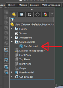
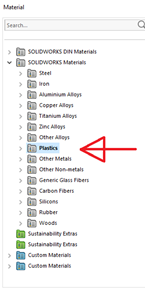
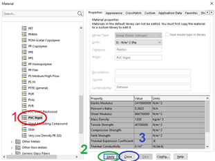
And there we go! Lastly, let’s set the material of the object to PVC. Do this by right clicking on the body in the feature tree and clicking on “material” > “edit material”. In the window that opens, click on the “plastics” folder. In this folder, find “PVC Rigid”. Click on it, and then click apply, then close.
The pipe should now be white, just like real PVC!
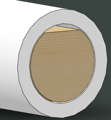
Next, we need to model the wooden plug that sits inside the end of the whistle.
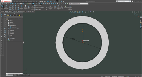
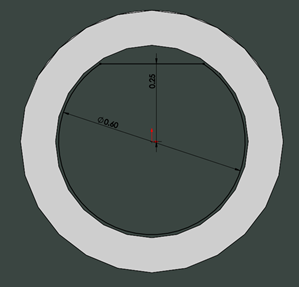
Click on sketch to create a new sketch and place it on the end of the whistle. Draw a circle just a little smaller than the inner diameter of the PVC, and set it’s diameter to 0.6”.
To create the flat top of the peg, draw a line across the top of the circle. Place both the beginning and the end of the line on the circle. Next set the line to horizontal, as shown above. Add a dimension from the origin to the line and set it to 0.25”. All lines in the sketch should be black.
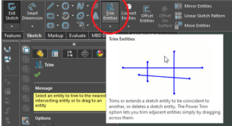
Next, remove the curve above the line using the “trim entities” tool. Click the tool, and click the top of the circle. That part of the circle should now be gone, and the sketch should be a single loop of lines.
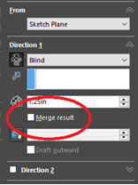
Next, we can extrude the sketch to form the plug. Click on extrude, and set the length to 1.25”. As this is a separate part, uncheck “merge result” in the extrude options. This causes the extrude to create a separate body, which we can set to be a different material.
We have the plug! At this point, the plug is the default grey. Let’s fix that. Under the bodies folder in the feature tree, there should now be 2 bodies. The second one is our plug. Using the same process as before, set it’s material to be wood. There is a woods folder just like a plastics folder. Open it and chose pine.
Now we have a wooden plug!
Next, let’s model the cap on the end.
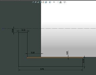
Create a sketch on the right plane, and go parallel to it (hit space, and click the cube’s side). Draw the shape of the cap, using the dimensions below. The construction line (dashed) in the middle is connected to the origin at the other end of the pipe and is horizontal. It’s needed in the next step, so remember to include it.
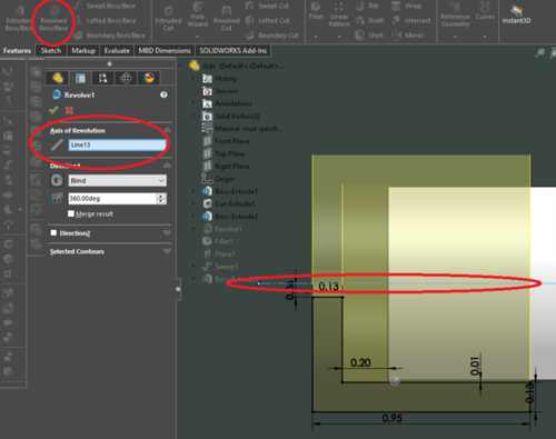
To turn this into the cap, a revolve is used. This spins the sketch around an axis to create a solid. In this case, the construction line is that axis. Select the revolve option, and if it does not automatically detect the center line (it did for me), click on the “axis of revolution” box and then select the line.
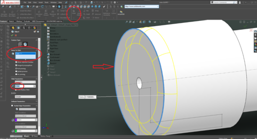
To round off the edges of the cap, let’s add a filet. Filets are an amazingly simple way to turn sharp corners into rounded edges. to add one, first click on the fillet tool, and then select the edge that you want to round off.
And we have a cap!
Once again, it’s a new body, so set it’s material to PVC just like the pipe body
The last thing to make is the slider that makes this a slide whistle.
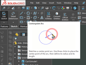
Start by creating a sketch on the right plane. On the sketch, draw a line that represents the path that the rod will follow. To make the curve on the end, use the centerpoint arc tool.
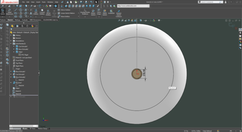
Next, we need to draw the outer shape of the rod. Create another sketch on the end of the cap and draw a 0.1” circle on the origin. Exit this sketch as well.
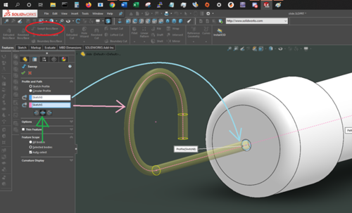
Next, a sweep is created using the 2 previous sketches. Select the sweep tool, select the 2 sketches, and select the Bidirectional option (green).
This creates a rod with a curve at the end.
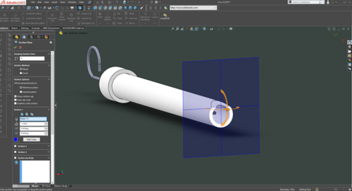
Next, we need to model the plastic plug that is attached to the end of the wire. As it is hidden inside the main body of the part, we need to do something to get access to it. Solidworks has a tool that makes this easy, called section view. To use it, click on the icon shown below:
This lets you drop a plane onto the part, and everything on the close side will be hidden. Don’t worry, it’s not gone. Just click the icon again to go back to the full part.
For this part, cut off the end of the pipe at the mouthpiece end.
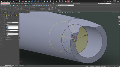
Then, create a new sketch on the end of the wire. Draw 2 circles, one the size of the wire, and the other a little smaller than the inner diameter of the pipe. Extrude this sketch to a length of ½”. Make sure that “merge result” is not checked.
And you’re done with the cad!
Make the parts
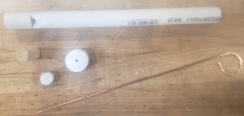
- Now, it’s time to build it. Materials required:
- ½” PVC
- ½” PVC cap with hole in end
- ½” dowel
- ½” delrin plug
- Welding rod
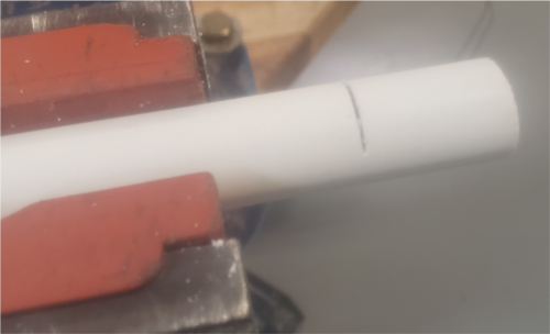
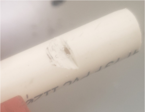
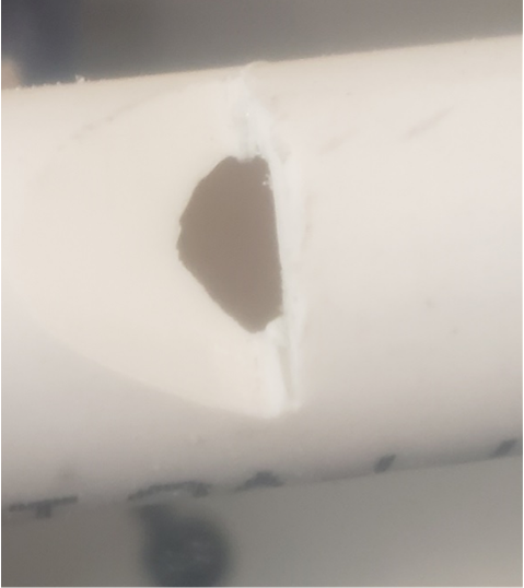
First, the notch in the pipe needs to be cut. It is important that this notch not be to large or to deep, as it will negatively effect the devices ability to make sound. Start by using a hacksaw to cut a small notch vertically into the pipe. Mount the pipe in the rubber vice clamps and cut just until through the wall of the pipe.
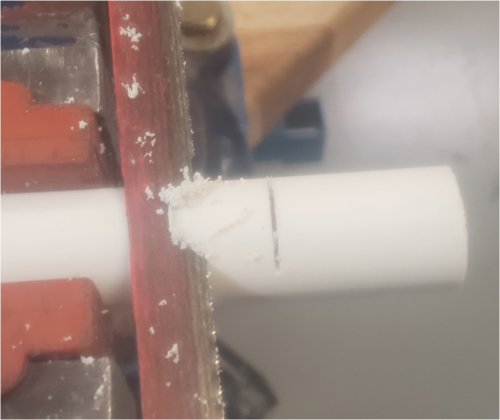
Next, cut in at an angle to form the notch. To start the cut, it is helpful to take a couple strokes vertically, and then cut in at an angle from that starting point.
Cut down to the vertical notch, removing the plastic triangle. The resulting notch will be rough, so next, use a wide file to smooth out the surface. Once the surface is smooth, remove the burs left on the inside of the cut with the deburring tool. Be careful not to remove too much material, as the tip of the notch needs to be thin and sharp to produce good sound.
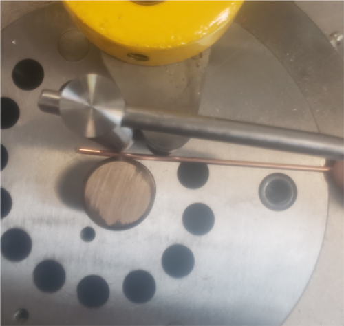
Next, we need to bend the loop on the end of the wire rod. To do this, we will use the wire bender, which has a tutorial *here*. Use the ½” center peg and clamp the wire against it as shown below.
Once the wire is clamped in place, use the bender to bend the wire around the center peg, forming a loop.
The last part to make before assembly is the wooden peg. The outer diameter should match the pipe’s inner diameter, but the flat side needs to be created. To do this, simply sand the peg against sand paper until a suitable flat surface is created.
Assembly
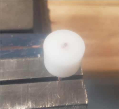
First, slide the cap onto the wire rod. Make sure it is pointing the right direction. Then, clamp the rod in the vice, with about ¾” protruding above it. Take the delrin cylinder, and using a mallet, gently pound it onto the wire. Stop once the wire is fully through the cylinder.
Lastly, slide the slide assembly into the pipe, and insert the wooden peg into the opposite end.
And you’re done!
