Difference between revisions of "Electronic keyboard"
Jump to navigation
Jump to search
| Line 1: | Line 1: | ||
| + | <style> | ||
| + | #rotate-text { | ||
| + | width: 25px; | ||
| + | transform: rotate(90deg); | ||
| + | } | ||
| + | </style> | ||
| + | |||
| + | |||
{{#set: | {{#set: | ||
|Is tv=True | |Is tv=True | ||
| Line 15: | Line 23: | ||
== Bill of Materials == | == Bill of Materials == | ||
| − | + | ||
* Keyboard PCB | * Keyboard PCB | ||
* Keyboard parts kit | * Keyboard parts kit | ||
| Line 22: | Line 30: | ||
==CAD== | ==CAD== | ||
| + | |||
| + | <div id="rotate-text"> | ||
| + | <p>My paragraph</p> | ||
| + | </div> | ||
For this TV, the cad has been done for you, as this is more of an exercise in assembly and programming than in design. | For this TV, the cad has been done for you, as this is more of an exercise in assembly and programming than in design. | ||
Revision as of 10:31, 8 June 2021
<style>
- rotate-text {
  width: 25px;
  transform: rotate(90deg);
} </style>
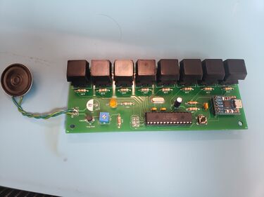
In this TV, we will be creating an electronic keyboard.
Bill of Materials
- Keyboard PCB
- Keyboard parts kit
- printed keyboard caps
- Solder
CAD
My paragraph
For this TV, the cad has been done for you, as this is more of an exercise in assembly and programming than in design.
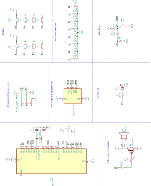
Here is the Schematic used for this build:
The processor is an ATmega328, the same processor as is used on the Arduino Uno. There are 8 button inputs, with pulldown resistors on the signal lines, and a speaker amplifier to drive a small speaker.
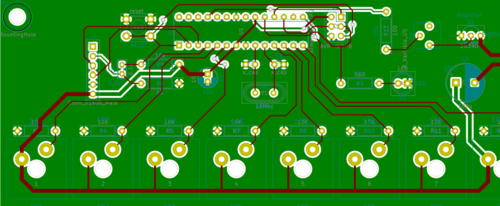
This schematic was used to create the following PCB:
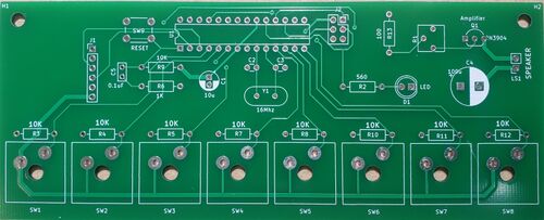
The cad file is sent to a manufacturer, and they send back a board that looks like this:


