Difference between revisions of "Hand Bender"
| Line 15: | Line 15: | ||
|Has imagedesc=Di-Acro Hand Bender | |Has imagedesc=Di-Acro Hand Bender | ||
|Has description=Di-Acro Hand Bender | |Has description=Di-Acro Hand Bender | ||
| − | |Has ace=Needed; | + | |Has ace=Needed;Makerhub@georgefox.edu |
}} | }} | ||
[[{{#show: {{FULLPAGENAME}}|?Has icon|link=none}}|140px|left|top|{{#show: {{FULLPAGENAME}}|?Has icondesc}}]] | [[{{#show: {{FULLPAGENAME}}|?Has icon|link=none}}|140px|left|top|{{#show: {{FULLPAGENAME}}|?Has icondesc}}]] | ||
Revision as of 09:44, 29 September 2022
Make: Di-Acro
Model: Model 2 Bender (02HB)
Serial Number: 111812
Ace: Needed (Makerhub@georgefox.edu).
Location: Machine Shop
Safety First
Here are some safety instructions for the Hand Bender. Remember... SAFETY FIRST!!!
- Keep all hands and fingers out of any pinch points.
- Be aware of your surroundings before swinging the bending handle.
Description
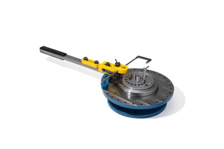
A hand bender is a machine used to bend wire, bar stock, and tubing using mechanical advantage. You can quickly bend hooks and other designs after setting up the machine with the correct tooling. It uses a variety of dies for different types of bends and radii.The bender is firmly mounted to the table in the Machine Shop.
Here is an example of bending a piece of rod:
Here is an example of bending a piece flat bar:
Documentation
Terminology
See the diagram on page 4 of the User Manual for complete terminology and visual reference.
- Radius pin - The dye that the stock is formed around. Sized by radius.
- The following sizes are available in the maker-hub: 1/8", 3/16", 1/2", 11/16", 1", 1 3/4".
- Locking pin - A cam pin used to lock the material against the radius pin. Depending on the application, using a holding pin instead of a locking pin may be easier.
- Holding pin - A pin used to brace the material against the radius pin. A holding pin may be used when there is enough material behind the desired bend to brace against the holding pin.
- Handle - The thing you grab to gain mechanical advantage and exert force on the material.
- Forming nose - The contact point between the handle and the material.
- Trigger - The lever- esc thing on top of the handle responsible for bracing the forming nose against bending in a particular direction. The trigger should always point in the direction that the handle is being pulled.
- Adjusting Bolt - NOT a technical term, used instead of "SCREW-HHCS 1/2-20X2". For the purposes of explaining how to use the hand bender, the adjusting bolt refers to the bolt that you loosen to adjust the distance between the forming nose is to the radius pin. See #27 on the figure on page 4 of the User Manual
Training
Operation
Read/skim the "Art of Bending" document to find out how to set up the equipment. Then Watch the "Simple Bend" video to see how the equipment functions.
Demonstration
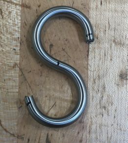
To demonstrate competency on the hand bender you will be required to make a s hook. A Training Venture (TV) that uses the hand bender is the Triangle.
General Procedure
1) Read and understand the terminology section of the wiki.
2) Gather all necessary supplies: 0.25" round mild steel stock, ruler, sharpie, hacksaw, 1/2" R radius pin, locking pin, 3/4" wrench.
3) Cut a piece of 0.25" round mild steel stock 6" long using a hacksaw. (A hacksaw should be used instead of the horizontal band-saw because the diameter of the material being cut is small enough that only one-two teeth on the band-saw blade will contact the material at a given time. The likelihood of damaging the saw blade or having the stock become caught in the blade increases anytime less than three teeth are in contact with the cut stock.)
4) Using a ruler and sharpie, mark the middle point and make a mark 1/8" from each end respectively.
5) Insert the 1/2" R radius pin into the center hole and place the locking pin in the 2nd closest hole.
6) Insert the 6" rod between the radius and locking pins. Tighten the cam such that the 1/8" mark is tangent to the radius pin. It is a tight fit so rocking the locking pin back and forth may be necessary to adjust properly.
7) As needed, use the 3/4" wrench adjust the adjusting bolt such that the locking pin does not interfere with the path of the forming nose. The middle position should work.
8) Ensure that the trigger is pointed in the correct direction (the direction you will pull the handle).
9) Bend the rod until the center mark on the rod barely touches the radius pin. The rod will spring back so a slight over-bend is necessary. You should have a p shape with a gap. *
10) Repeat step 5 for the opposite end with the p shape facing the forming nose.
11) Bend the rod until the center mark on the rod barely touches the radius pin. *
12) Since the forming nose is applying a force to the nice p you had, it will be slightly deformed. To Fix this, simply put the deformed side around the radius pin and re-bend it until you are satisfied with the shape.
13) Reset the space.
* If the rod slips loose during the bending process tighten the locking pin and adjust the location slightly. If the issue persists try clamping the center of the rod between the radius and locking pins and bending about this point.
Certification
Troubleshooting
This is a very basic piece of equipment so very little trouble shooting should be required. See the "Art of Bending" document for machine setup.
Maintenance
General maintenance
Tech will lubricate zerk fitting as needed.
Specific Maintenance Tasks
| Maintenance Procedure | Frequency | Done By |
|---|---|---|
| Grease rotation Zerk | As needed | Technician |


