Difference between revisions of "Waterjet Cutter"
| Line 40: | Line 40: | ||
====Terminology==== | ====Terminology==== | ||
| + | * Tool path - The path that the water jet will follow when cutting out a part. This includes more than just the outline of the part because the water jet must pierce through the material before performing a cut. | ||
| − | + | ==== User Manuals ==== | |
| − | + | [https://knowledgebase.omax.com/protomax/content/accessories-home.htm?tocpath=MANUALS%7CACCESSORY%20%20GUIDES%7C_____0 Complete list of ProtoMAX manuals] | |
| − | |||
==Training== | ==Training== | ||
====Overview==== | ====Overview==== | ||
| − | + | The water jet cutter is an amazing tool that can be used on a wide variety of materials including 1" steel! However, it is limited to a 12" by 12" cut area with a 1" thickness being its maximum. Make sure the water jet cutter is capable of handling your part and your material before going through all of the setup procedures. Like cutting many other two dimensional cutting tools, the cutting process should begin with a DXF file created from Solidworks or a similar software. Once a DXF fie has been created it can then be used to create a tool path using ProtoMAX layout. The detailed steps to do do this can be found in the general procedure but the most important part is to ensure that the water jet pierces the material outside of the part outline. After the tool path is created and the machine has been properly set up, the job can be posted to the MAKE software, which is installed on the water jet's computer , to perform the cut. | |
| + | |||
| + | The water jet can be a very dangerous machine if not used properly so here are some important safety items to keep in mind. First, Jesus forgives, but 30,000 psi doesn't. So pay attention to these precautions and be safe while operating this machine. | ||
| + | # NEVER, EVER, EVER, EVER, EVER turn on the machine without first turning on the water! You could destroy the machine...and your reputation. | ||
| + | # If you see water squirting out the side of the machine while running a cut, don't touch it! It is the fountain of "Bye Bye Fingers." | ||
| + | # Wear rubber gloves while dealing with the water in the tank. The water in there is a nasty pool of bacteria and chemicals just waiting to crawl into your open wounds. | ||
| + | # If you're an idiot and manage to run the water jet while your hand is underneath it, you have the opportunity of going to the ER and taking with you a medical card that tells the doctors how to treat you so you don't die. | ||
====Demonstration==== | ====Demonstration==== | ||
| Line 60: | Line 66: | ||
==Certification== | ==Certification== | ||
| − | + | [https://foxtale.georgefox.edu/moodle/enrol/index.php?id=31413 Water Jet FoxTALE Course] | |
==Troubleshooting== | ==Troubleshooting== | ||
| Line 80: | Line 86: | ||
|} | |} | ||
| − | + | <br /> | |
| − | |||
| − | |||
| Line 93: | Line 97: | ||
'''Reset The Space.''' Always clean the machine when finished and follow the proper shutdown procedures. | '''Reset The Space.''' Always clean the machine when finished and follow the proper shutdown procedures. | ||
| − | '''Be Professional.''' Always be attentive while cutting, and never leave the machine while using it. | + | '''Be Professional.''' Always be attentive while cutting, and never leave the machine while using it.w |
| − | |||
| − | |||
| − | |||
| − | |||
| − | |||
| − | |||
| − | |||
== Training == | == Training == | ||
'''Will it work for your part?''' | '''Will it work for your part?''' | ||
| − | |||
| − | |||
'''Designing the Part and Creating the Tool Paths''' | '''Designing the Part and Creating the Tool Paths''' | ||
| − | |||
| − | |||
'''Part Design in ProtoMAX LAYOUT''' | '''Part Design in ProtoMAX LAYOUT''' | ||
| − | # Open ProtoMAX LAYOUT. Your screen should look something like this. <br /> <figure-inline><figure-inline><figure-inline>[[File:ProtoMAX_LAYOUT.png|600x600px]]</figure-inline></figure-inline></figure-inline> <br /> <br /> | + | # Open ProtoMAX LAYOUT. Your screen should look something like this. <br /> <figure-inline><figure-inline><figure-inline><figure-inline>[[File:ProtoMAX_LAYOUT.png|600x600px]]</figure-inline></figure-inline></figure-inline></figure-inline> <br /> <br /> |
| − | #Select the "Line" tool from the "Draw" menu on the left of the screen and create a 2" square with a 1" square notch in the top right corner. To do this, click anywhere on the screen to start the first line. This will bring a popup "Specify Dimensions" box where you will enter 2 into the "Rise (dy)" box. This will create a 2" vertical line. Select the "Line" tool again at the top of the first line and enter 1 into the "Run (dx)" box. This will create a 1" horizontal line to the right. Repeat this process until the box looks like this. The last line at the bottom can by created by selecting both open edges with the "Line" tool. <br /> <figure-inline><figure-inline><figure-inline>[[File:Basic_shape_of_box.png|600x600px]]</figure-inline></figure-inline></figure-inline> <br /> <br /> | + | #Select the "Line" tool from the "Draw" menu on the left of the screen and create a 2" square with a 1" square notch in the top right corner. To do this, click anywhere on the screen to start the first line. This will bring a popup "Specify Dimensions" box where you will enter 2 into the "Rise (dy)" box. This will create a 2" vertical line. Select the "Line" tool again at the top of the first line and enter 1 into the "Run (dx)" box. This will create a 1" horizontal line to the right. Repeat this process until the box looks like this. The last line at the bottom can by created by selecting both open edges with the "Line" tool. <br /> <figure-inline><figure-inline><figure-inline><figure-inline>[[File:Basic_shape_of_box.png|600x600px]]</figure-inline></figure-inline></figure-inline></figure-inline> <br /> <br /> |
# Select the "Circle" tool and choose the intersect option from the bottom of the screen. Click the top, left corner of the square and enter 0.5 for the diameter of the circle. | # Select the "Circle" tool and choose the intersect option from the bottom of the screen. Click the top, left corner of the square and enter 0.5 for the diameter of the circle. | ||
# Select the circle using the "Select" tool from the "Edit" menu on the left of the screen (make sure to select the top and bottom of the circle). Next, select the "Move" tool from the left side of the screen and choose the "Intersect" option from the bottom of the screen. | # Select the circle using the "Select" tool from the "Edit" menu on the left of the screen (make sure to select the top and bottom of the circle). Next, select the "Move" tool from the left side of the screen and choose the "Intersect" option from the bottom of the screen. | ||
| − | #Click on the center of the circle where the corner of the square is and enter 0.5 and -0.5 for the "Run" and "Rise" of the movement. Your screen should look something like this. <br /> <figure-inline><figure-inline><figure-inline>[[File:Box_with_circle.png|600x600px]]</figure-inline></figure-inline></figure-inline> <br /> <br /> | + | #Click on the center of the circle where the corner of the square is and enter 0.5 and -0.5 for the "Run" and "Rise" of the movement. Your screen should look something like this. <br /> <figure-inline><figure-inline><figure-inline><figure-inline>[[File:Box_with_circle.png|600x600px]]</figure-inline></figure-inline></figure-inline></figure-inline> <br /> <br /> |
'''Tool Paths''' | '''Tool Paths''' | ||
| Line 124: | Line 117: | ||
Before showing you how to create a tool path, there are a couple of things that you must keep in mind. When the water jet cuts, it cuts on the left side of a line from the direction it is moving in. Because of this, you must control the direction that the nozzle will travel. For an outside cut, you want it to cut on the outside of the line to preserve the proper dimensions of the part. For and inside cut, you want the opposite of that. For a ring, you would want the nozzle to travel clockwise for the outside cut and counter-clockwise for the inside cut. To control the direction of the nozzle, you place lead-in and lead-out lines. Its how you specify the start or end of a cut and the cut direction. Lastly, it is better to cut the inner bits first and then the outer bits last; and if you can help it, don't let the nozzle travel over any holes that were already cut. | Before showing you how to create a tool path, there are a couple of things that you must keep in mind. When the water jet cuts, it cuts on the left side of a line from the direction it is moving in. Because of this, you must control the direction that the nozzle will travel. For an outside cut, you want it to cut on the outside of the line to preserve the proper dimensions of the part. For and inside cut, you want the opposite of that. For a ring, you would want the nozzle to travel clockwise for the outside cut and counter-clockwise for the inside cut. To control the direction of the nozzle, you place lead-in and lead-out lines. Its how you specify the start or end of a cut and the cut direction. Lastly, it is better to cut the inner bits first and then the outer bits last; and if you can help it, don't let the nozzle travel over any holes that were already cut. | ||
| − | # Zoom in closer to the circle. Select the "Lead i/o" tool from the "Draw" menu on the left of the screen. Select the bottom edge of the circle and move the cursor upwards and click to create a lead in and out from the center of the circle. This will tell the water jet to cut on the inside of the circle. Looking at this picture, you can see that one line is longer than the other. This longer line is the lead-in line. The nozzle will penetrate the material from the beginning of the long line and work its way down to the bottom of the circle. Once the nozzle hits the bottom, it will start counter-clockwise because the lead-in line is positioned at a slight angle to make counter-clockwise and easier direction than clockwise. This is how you tell the nozzle which direction to cut. <br /> <figure-inline><figure-inline><figure-inline>[[File:Lead i-o.png|600x600px]]</figure-inline></figure-inline></figure-inline> <br /> <br /> | + | # Zoom in closer to the circle. Select the "Lead i/o" tool from the "Draw" menu on the left of the screen. Select the bottom edge of the circle and move the cursor upwards and click to create a lead in and out from the center of the circle. This will tell the water jet to cut on the inside of the circle. Looking at this picture, you can see that one line is longer than the other. This longer line is the lead-in line. The nozzle will penetrate the material from the beginning of the long line and work its way down to the bottom of the circle. Once the nozzle hits the bottom, it will start counter-clockwise because the lead-in line is positioned at a slight angle to make counter-clockwise and easier direction than clockwise. This is how you tell the nozzle which direction to cut. <br /> <figure-inline><figure-inline><figure-inline><figure-inline>[[File:Lead i-o.png|600x600px]]</figure-inline></figure-inline></figure-inline></figure-inline> <br /> <br /> |
| − | # Next, place a "Lead i/o" near the bottom of the left wall on the square moving your cursor to the left and clicking to tell the machine to cut on the outside of the box. <br /> <figure-inline><figure-inline><figure-inline>[[File:Lead io2.png|600x600px]]</figure-inline></figure-inline></figure-inline> <br /> <br /> | + | # Next, place a "Lead i/o" near the bottom of the left wall on the square moving your cursor to the left and clicking to tell the machine to cut on the outside of the box. <br /> <figure-inline><figure-inline><figure-inline><figure-inline>[[File:Lead io2.png|600x600px]]</figure-inline></figure-inline></figure-inline></figure-inline> <br /> <br /> |
# Select the "Line" tool and connect the long, lead-in line of the box to the short, lead-out line of the circle. This is a traverse line telling the machine to move from the circle to the box after it has finished cutting the circle. | # Select the "Line" tool and connect the long, lead-in line of the box to the short, lead-out line of the circle. This is a traverse line telling the machine to move from the circle to the box after it has finished cutting the circle. | ||
| − | # Use the line tool and click on the long, lead-in line for the circle. Place the other end of the line so that it is at least 1/8" past both the left and bottom edge of the part. This will be the origin for the part and the cut. It should look something like this. <br /> <figure-inline><figure-inline><figure-inline>[[File:Design with traverse lines.png|600x600px]]</figure-inline></figure-inline></figure-inline> <br /> <br /> | + | # Use the line tool and click on the long, lead-in line for the circle. Place the other end of the line so that it is at least 1/8" past both the left and bottom edge of the part. This will be the origin for the part and the cut. It should look something like this. <br /> <figure-inline><figure-inline><figure-inline><figure-inline>[[File:Design with traverse lines.png|600x600px]]</figure-inline></figure-inline></figure-inline></figure-inline> <br /> <br /> |
| − | # Now you get to decide the quality of each cut. Select the button at the bottom of your screen labeled "Quality". You should see a range from 1 to 5, a Traverse, and Lead i/o. The range of 1 to 5 will change the machines cutting speed. The higher quality is 5 (slower) and the lowest quality is 1 (faster). Choose a quality of 5 for the circle by clicking "5" and then selecting every part of the circle. Do the same for the outer edge but with a quality of 1. Your part should look like this. Leave the traverse lines as green. You don't want them to cut there. <br /> <figure-inline><figure-inline><figure-inline>[[File:Quality lines.png|600x600px]]</figure-inline></figure-inline></figure-inline> <br /> <br /> | + | # Now you get to decide the quality of each cut. Select the button at the bottom of your screen labeled "Quality". You should see a range from 1 to 5, a Traverse, and Lead i/o. The range of 1 to 5 will change the machines cutting speed. The higher quality is 5 (slower) and the lowest quality is 1 (faster). Choose a quality of 5 for the circle by clicking "5" and then selecting every part of the circle. Do the same for the outer edge but with a quality of 1. Your part should look like this. Leave the traverse lines as green. You don't want them to cut there. <br /> <figure-inline><figure-inline><figure-inline><figure-inline>[[File:Quality lines.png|600x600px]]</figure-inline></figure-inline></figure-inline></figure-inline> <br /> <br /> |
# Sometimes there are extra points or lines that are unnecessary. Click "Clean" on the right side of your screen, click "start" on the popup window, and "okay" on the second popup window. Now your tool path is cleaned. | # Sometimes there are extra points or lines that are unnecessary. Click "Clean" on the right side of your screen, click "start" on the popup window, and "okay" on the second popup window. Now your tool path is cleaned. | ||
# The last step is saving the file to be cut. Click "Post" on the right of your screen. This may ask you to save your drawing; do so. It will then bring you to a window asking you to "Pick Start". Select end of the traverse line that you defined as the origin. | # The last step is saving the file to be cut. Click "Post" on the right of your screen. This may ask you to save your drawing; do so. It will then bring you to a window asking you to "Pick Start". Select end of the traverse line that you defined as the origin. | ||
| Line 154: | Line 147: | ||
== Water Jet Precautions == | == Water Jet Precautions == | ||
| − | + | # | |
| − | |||
| − | # | ||
| − | |||
| − | |||
| − | |||
Revision as of 16:56, 31 May 2019
-

Make: OMAX
Model: ProtoMAX
Ace: Mikayla Stephenson (mstephenson22@georgefox.edu).
Location: Machine Shop
Description
The Water jet Cutter is a machine that uses highly pressurized water with a flow of an abrasive material to perform computer controlled cuts on a wide variety of materials, including 1" steel. This is helpful for creating parts with intricate designs for car engines, mounting brackets, and decorative plates. Another benefit of the water jet is that there is minimal temperature change during the process which makes it perfect for cutting temperature sensitive materials. Check out the video below to see the water jet in action.
Documentation
Terminology
- Tool path - The path that the water jet will follow when cutting out a part. This includes more than just the outline of the part because the water jet must pierce through the material before performing a cut.
User Manuals
Complete list of ProtoMAX manuals
Training
Overview
The water jet cutter is an amazing tool that can be used on a wide variety of materials including 1" steel! However, it is limited to a 12" by 12" cut area with a 1" thickness being its maximum. Make sure the water jet cutter is capable of handling your part and your material before going through all of the setup procedures. Like cutting many other two dimensional cutting tools, the cutting process should begin with a DXF file created from Solidworks or a similar software. Once a DXF fie has been created it can then be used to create a tool path using ProtoMAX layout. The detailed steps to do do this can be found in the general procedure but the most important part is to ensure that the water jet pierces the material outside of the part outline. After the tool path is created and the machine has been properly set up, the job can be posted to the MAKE software, which is installed on the water jet's computer , to perform the cut.
The water jet can be a very dangerous machine if not used properly so here are some important safety items to keep in mind. First, Jesus forgives, but 30,000 psi doesn't. So pay attention to these precautions and be safe while operating this machine.
- NEVER, EVER, EVER, EVER, EVER turn on the machine without first turning on the water! You could destroy the machine...and your reputation.
- If you see water squirting out the side of the machine while running a cut, don't touch it! It is the fountain of "Bye Bye Fingers."
- Wear rubber gloves while dealing with the water in the tank. The water in there is a nasty pool of bacteria and chemicals just waiting to crawl into your open wounds.
- If you're an idiot and manage to run the water jet while your hand is underneath it, you have the opportunity of going to the ER and taking with you a medical card that tells the doctors how to treat you so you don't die.
Demonstration
Insert text
General Procedure
Insert text
Certification
Troubleshooting
Maintenance
General maintenance
Insert text
Specific Maintenance Tasks
| Maintenance Procedure | Frequency | Done By |
|---|---|---|
| Sample | Sample | Sample |
3 commandments
Stuff about the 3 commandments.
Safety First. The water jet cutter can be a dangerous machine if not used properly.
Reset The Space. Always clean the machine when finished and follow the proper shutdown procedures.
Be Professional. Always be attentive while cutting, and never leave the machine while using it.w
Training
Will it work for your part?
Designing the Part and Creating the Tool Paths
Part Design in ProtoMAX LAYOUT
- Open ProtoMAX LAYOUT. Your screen should look something like this.
<figure-inline><figure-inline><figure-inline><figure-inline>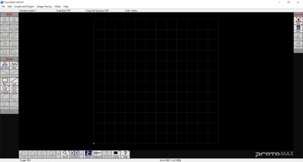 </figure-inline></figure-inline></figure-inline></figure-inline>
- Select the "Line" tool from the "Draw" menu on the left of the screen and create a 2" square with a 1" square notch in the top right corner. To do this, click anywhere on the screen to start the first line. This will bring a popup "Specify Dimensions" box where you will enter 2 into the "Rise (dy)" box. This will create a 2" vertical line. Select the "Line" tool again at the top of the first line and enter 1 into the "Run (dx)" box. This will create a 1" horizontal line to the right. Repeat this process until the box looks like this. The last line at the bottom can by created by selecting both open edges with the "Line" tool.
<figure-inline><figure-inline><figure-inline><figure-inline>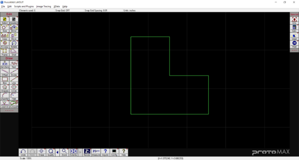 </figure-inline></figure-inline></figure-inline></figure-inline>
- Select the "Circle" tool and choose the intersect option from the bottom of the screen. Click the top, left corner of the square and enter 0.5 for the diameter of the circle.
- Select the circle using the "Select" tool from the "Edit" menu on the left of the screen (make sure to select the top and bottom of the circle). Next, select the "Move" tool from the left side of the screen and choose the "Intersect" option from the bottom of the screen.
- Click on the center of the circle where the corner of the square is and enter 0.5 and -0.5 for the "Run" and "Rise" of the movement. Your screen should look something like this.
<figure-inline><figure-inline><figure-inline><figure-inline>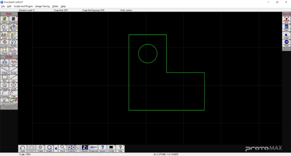 </figure-inline></figure-inline></figure-inline></figure-inline>


Tool Paths
Most of the time, you will not be using ProtoMAX LAYOUT to design a part. Thankfully, this program can accept ".dxf" files, but you still have to create the tool paths. If using a ".dxf" file, import the file to skip the last section and start here to give it a tool path.
Before showing you how to create a tool path, there are a couple of things that you must keep in mind. When the water jet cuts, it cuts on the left side of a line from the direction it is moving in. Because of this, you must control the direction that the nozzle will travel. For an outside cut, you want it to cut on the outside of the line to preserve the proper dimensions of the part. For and inside cut, you want the opposite of that. For a ring, you would want the nozzle to travel clockwise for the outside cut and counter-clockwise for the inside cut. To control the direction of the nozzle, you place lead-in and lead-out lines. Its how you specify the start or end of a cut and the cut direction. Lastly, it is better to cut the inner bits first and then the outer bits last; and if you can help it, don't let the nozzle travel over any holes that were already cut.
- Zoom in closer to the circle. Select the "Lead i/o" tool from the "Draw" menu on the left of the screen. Select the bottom edge of the circle and move the cursor upwards and click to create a lead in and out from the center of the circle. This will tell the water jet to cut on the inside of the circle. Looking at this picture, you can see that one line is longer than the other. This longer line is the lead-in line. The nozzle will penetrate the material from the beginning of the long line and work its way down to the bottom of the circle. Once the nozzle hits the bottom, it will start counter-clockwise because the lead-in line is positioned at a slight angle to make counter-clockwise and easier direction than clockwise. This is how you tell the nozzle which direction to cut.
<figure-inline><figure-inline><figure-inline><figure-inline>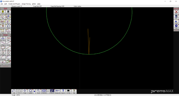 </figure-inline></figure-inline></figure-inline></figure-inline>
- Next, place a "Lead i/o" near the bottom of the left wall on the square moving your cursor to the left and clicking to tell the machine to cut on the outside of the box.
<figure-inline><figure-inline><figure-inline><figure-inline>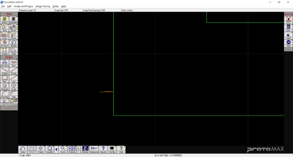 </figure-inline></figure-inline></figure-inline></figure-inline>
- Select the "Line" tool and connect the long, lead-in line of the box to the short, lead-out line of the circle. This is a traverse line telling the machine to move from the circle to the box after it has finished cutting the circle.
- Use the line tool and click on the long, lead-in line for the circle. Place the other end of the line so that it is at least 1/8" past both the left and bottom edge of the part. This will be the origin for the part and the cut. It should look something like this.
<figure-inline><figure-inline><figure-inline><figure-inline>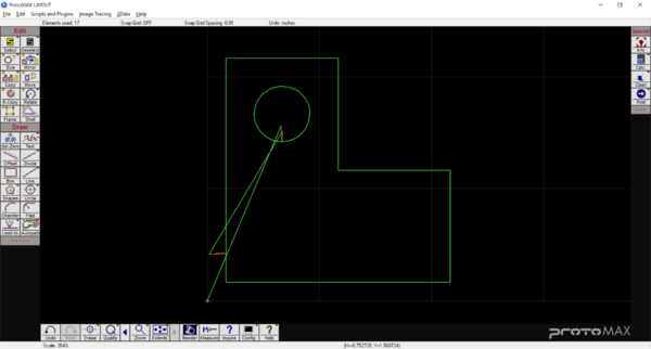 </figure-inline></figure-inline></figure-inline></figure-inline>
- Now you get to decide the quality of each cut. Select the button at the bottom of your screen labeled "Quality". You should see a range from 1 to 5, a Traverse, and Lead i/o. The range of 1 to 5 will change the machines cutting speed. The higher quality is 5 (slower) and the lowest quality is 1 (faster). Choose a quality of 5 for the circle by clicking "5" and then selecting every part of the circle. Do the same for the outer edge but with a quality of 1. Your part should look like this. Leave the traverse lines as green. You don't want them to cut there.
<figure-inline><figure-inline><figure-inline><figure-inline>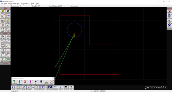 </figure-inline></figure-inline></figure-inline></figure-inline>
- Sometimes there are extra points or lines that are unnecessary. Click "Clean" on the right side of your screen, click "start" on the popup window, and "okay" on the second popup window. Now your tool path is cleaned.
- The last step is saving the file to be cut. Click "Post" on the right of your screen. This may ask you to save your drawing; do so. It will then bring you to a window asking you to "Pick Start". Select end of the traverse line that you defined as the origin.
- A window will popup showing the tool path. Zoom in closer to your part and inspect where the tool path is. The program will display cuts as a thick red line. Make sure that these projected cut lines are on the proper side of the line that you specified. If all looks well, hit "save" on the bottom, left of your screen.


Operation Procedures
- Open the water valve
- Check the pressure gauge to verify that the water pressure is 40 psi or greater
- Fill the tank to the top of the metal ribs
- Check the garnet hopper. If it is low, fill it up.
- Power on the computer and plug in the USB
- Power on the water jet cutter
- Open MAKE
- Zero the water jet cutter head
- Position the nozzle between two of the metal ribs, close the lid, and test the nozzle
- Open the lid, position the material in the machine, and clamp it down
- Load the cut file, select the material and enter its thickness
- Set the origin point for the machine
- Position the nozzle over the material and adjust the height of the nozzle very carefully making sure the adjustment tool has enough room to wiggle up and down
- Continue to fill the tank with more water so that there is about 1/8" of water above the surface of the material
- Execute a dry run making sure that the nozzle will not collide with anything
- Flip the orange rubber cone down, run the cut, and watch out for:
- Material excess floating up; pieces of cut material floating up and getting wedged between the nozzle and other material or clamps could cause a catastrophic failure. Pause the cut if you think this may happen.