Pick and Place
Make: LPKF
Model: Protoplace S
Serial Number: 0Z2701L006
Ace: Karson Rhoads (krhoads20@georgefox.edu).
Location: PCB Lab
Description
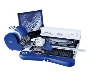
Pick & Place (Protoplace S) is a semi-automatic pick & place system for the professional assembly of Surface Mount Technology (SMT) printed circuit board prototypes and small batch projects. It is capable of dispensing solder paste, glues, and adhesives, but we typically use it just for placing minuscule components on PCBs.
Documentation
Terminology
- Micro-Table
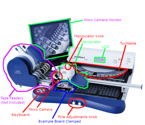
- This clamps PCBs as large as 297mm x 420mm (11.8” x 16.5”). Knobs at the front of the micro-table allow for fine adjustments along the X and Y axes, which are ideal for the placement of complex components.
- Manipulator
- The manipulator is what picks & places components. It is also capable of dispensing solder paste, glues, and adhesives with the dispenser attachment, however, we will not use these features. The manipulator can reach everywhere on the micro-table that will be needed for projects, including the turntable. The manipulator uses the vacuum and appropriate needle attachment in order to pick & place components.
- Manipulator Knob
- The knob above the box on the manipulator rotates the nozzle; so it rotates components sucked on the knob.
- Turntable
- The turntable is what houses the components used in the project. The turntable can be controlled using the keyboard and LCD display.
- Micro Camera and Monitor
- The micro camera captures the end of the nozzle so that you can view (on the monitor) an accurate representation of where the component will be placed.
Training
Operation
The Pick and Place organizes and helps place minuscule surface mount components by using a vacuum and a nozzle that is triggered by the amount of pressure applied to the nozzle (pushing down on a component).
Demonstration
To show a complete knowledge of the Pick and Place, the Student will have a PCB Prepared by the PCB Printer and follow the instructions in the General Procedure.
General Procedure
- Turn on the machine. The switch is located in the back left (if viewed from the front of the machine).
- Ensure that the correct vacuum tip is attached to the manipulator. If the tip is larger than the parts you are trying to pick up, then you need to change out the tip for something smaller. You can change tips for various sized components during the process.
- Do not use nozzles too large or the component will get sucked into the machine and the machine will get damaged.
- Place all of the parts needed for the project into their own sections on the turntable.
- It would be a good idea to have a separate section for each component for organization purposes (for yourself and others).
- Use a sticky note or labeling system of some sort for different components like resistor values.
- Turn on the monitor that will display the output of the micro camera. This will help you view your part while you are placing it on the pads.
- Clamp your board onto the microtable. You should not be able to move your board when it is secured.
- On the LCD, using the keyboard:
- Place -> auto/manual.
- Manual mode will only turn on the vacuum when sufficient pressure is applied to the nozzle (when you press the nozzle onto a component).
- Auto mode will always have the vacuum enabled.
- Let's assume we are in manual mode for the remainder of this procedure (easier because you can't accidentally pick up components). Move the manipulator to the desired component. Grab the component by pushing the nozzle down onto the surface of the component.
- Be sure that the component is not upside down!
- Move the manipulator and component to the position that the footprint is located (it doesn’t have to be exact yet). Using the keyboard and LCD screen, hit the Break option on the right of the LCD screen. This locks the manipulator so you cannot move it like you normally do which makes it easy to place your components.
- You can use the fine knobs on the front of the pick and place to make precise movements as well as the camera to assure you are placing it correctly on the pads.
- A higher resolution view can be seen on the monitor that’s output from the micro camera.
- Using the keyboard and LCD screen, hit the Place option. It places the component straight down for you!
- Repeat this process until all components are placed.
- Upon completion, refer to the instructions on the Reflow Oven wiki. The solder has not been solidified yet, so be careful with your board so you do not move components. Remember to select the correct setting: V1 Paste if you are using Voltera's special Ink and Paste, and Sn63Pb37 for prefabricated PCBs.
- RESET THE SPACE! Remove any notes and clean up any lost components.
Safety
There is almost nothing you can do on this device that will hurt you. If you place your hand under the nozzle and then smash down the nozzle, you will hurt yourself. Do not do this for obvious reasons.
However, there are things that can hurt the Pick and Place.
- Be gentle with how you treat the nozzle; press down gently when picking and placing components.
- Be sure to use a smaller nozzle than the component you are trying to place! Failure to do this results in sucking up the component into the nozzle which can clog it and prevent the vacuum from being effectively used.
Certification
Troubleshooting
- There are two monitors above the pick and place machine. You’ll want to have your Altium Schematic on one and the altium PCBDoc opened up so you can follow along as you’re placing and double checking things while you’re going.
- Don’t try to get the component exactly at the location of the pads without the break. It’s quicker if you get it in the general area and use the fine adjustments knob after placing the break.
- Pivot the micro camera to view alignments on both the x and y axes (again, the fine adjustment knobs are used here).
- If your tip is having a hard time keeping the component secure, try a bigger one.
- Be sure to use a smaller nozzle than the component you are trying to place! Failure to do this results in sucking up the component into the nozzle which can clog it and prevent the vacuum from being effectively used.
Maintenance
General maintenance
The Pick and Place has a few items that need to be maintained by the student or the Ace. Refer to the table below to see each procedure and how often it should occur.
Specific Maintenance Tasks
| Maintenance Procedure | Frequency | Done By |
|---|---|---|
| General Cleaning | Before and after use. Clean solder off of nozzle and clean table of loose components. | Student |
| Nozzle Change | Only when a component has been sucked up into the nozzle. | Student and Ace |

