Difference between revisions of "F370 3D Printer"
| (48 intermediate revisions by 8 users not shown) | |||
| Line 1: | Line 1: | ||
| − | [[{{# | + | [[File:..f370.jpg|thumb|412x412px]] |
| − | + | {{#set: | |
| + | |Is equipment=True | ||
| + | |Is located in facility=Prototype Lab | ||
| + | |Is used in domain=Electronics | ||
| + | |Has name={{PAGENAME}} | ||
| + | |Has icon= | ||
| + | |Has icondesc= | ||
| + | |Has image= | ||
| + | |Has imagedesc= | ||
| + | |Has description= | ||
| + | |Has certification=https://georgefox.instructure.com/courses/1229 | ||
| + | |Has make=Stratasys | ||
| + | |Has model=F370 | ||
| + | |Has serial number=D-30365 (Alpha) / D-30809 (Omega) | ||
| + | |Has group=Prototype Lab | ||
| + | |Has ace=Kyler Howard;khoward19@georgefox.edu | ||
| + | }} | ||
| + | [[File:F370 3D printer.png|left|140x140px|frameless]] | ||
Make: {{#show: {{PAGENAME}} |?Has make}} | Make: {{#show: {{PAGENAME}} |?Has make}} | ||
Model: {{#show: {{PAGENAME}} |?Has model}} | Model: {{#show: {{PAGENAME}} |?Has model}} | ||
| + | |||
| + | Serial Number: {{#show: {{PAGENAME}} |?Has serial number}} | ||
Ace: {{#show: {{PAGENAME}} |?Has ace.Has name}} ({{#show: {{PAGENAME}} |?Has ace.Has email address}}). | Ace: {{#show: {{PAGENAME}} |?Has ace.Has name}} ({{#show: {{PAGENAME}} |?Has ace.Has email address}}). | ||
| Line 14: | Line 33: | ||
==Description== | ==Description== | ||
| − | The F370 is an [[Prototype Lab#FDM Printing Anchor|FDM]] (fused deposit modeling) printer made by Stratasys. It is capable of producing highly accurate parts, whether for prototyping or functional use. The F370 shares the same brand and concept as the [[Dimension 3D Printer|Dimension]] printer, but with subtle differences in operation and maintenance. The F370 boasts the largest build plate in the Prototype lab. Combined with its high accuracy and consistency, the F370 can be left overnight to print multiple parts | + | The F370 is an [[Prototype Lab#FDM Printing Anchor|FDM]] (fused deposit modeling) printer made by Stratasys. It is capable of producing highly accurate parts, whether for prototyping or functional use. The F370 shares the same brand and concept as the [[Dimension 3D Printer|Dimension]] printer, but with subtle differences in operation and maintenance. The F370 boasts the largest build plate in the Prototype lab. Combined with its high accuracy and consistency, the F370 can be left overnight to print multiple parts prepared throughout the day with little worry about print failures. |
| − | The Stratasys printers utilize dissolving support material that leaves no surface damage from breaking off supports and allows for creative parts that are impossible on other printers. This printer is a great option for highly detailed or complex parts, parts containing holes that require high tolerances, parts that take advantage of the dissolving support material, bulk prints, or overflow from the Prusa printers when they are full. Currently, the Prototype Lab has two F370 printers available for use. | + | The Stratasys printers utilize dissolving support material that leaves no surface damage from breaking off supports and allows for creative parts that are impossible on other printers. This printer is a great option for highly detailed or complex parts, parts containing holes that require high tolerances, parts that take advantage of the dissolving support material, bulk prints, or overflow from the Prusa printers when they are full. Currently, the Prototype Lab has two F370 printers available for use. Printing parts on the F370 costs more than printing on the Prusa printers. If your part will cost more than $12 to print you will need to get approval from the supervisor on shift. |
| − | + | {{#evu:https://www.youtube.com/watch?v=W8K4YTekXRw}} | |
==Documentation== | ==Documentation== | ||
| Line 24: | Line 43: | ||
====Terminology==== | ====Terminology==== | ||
| − | + | <gallery> | |
| + | File:F370 Touchscreen.jpg|Touchscreen | ||
| + | File:...storageDrawer.png|Storage Drawer | ||
| + | File:...materialBayDrawer.png|Material Bay Drawer | ||
| + | File:...buildPlate.jpg|Build Plate | ||
| + | File:...materialSpool.jpg|Material Spool | ||
| + | </gallery> | ||
| + | |||
| + | [[Media:F170 F270 F370 User Guide - English.pdf|F370 3D Printer User Manual]] | ||
[https://www.stratasys.com/3d-printers/f123 Product Home Page] | [https://www.stratasys.com/3d-printers/f123 Product Home Page] | ||
| − | + | [https://help.grabcad.com/ GrabCAD Help Page] | |
==Training== | ==Training== | ||
| − | ==== | + | ====Operation==== |
| − | The basic workflow for using the F370 will be as follows: Preparing the Printer, Preparing Your File for Print, Printing Your Part, Soaking Your Part. First, you prepare the printer so that it is physically ready to print any design you give it. Second, you prepare the part on the software used by the F370. This generates a file | + | The basic workflow for using the F370 will be as follows: Preparing the Printer, Preparing Your File for Print, Printing Your Part, Soaking Your Part. First, you prepare the printer so that it is physically ready to print any design you give it. Second, you prepare the part on the software used by the F370. This generates a file that tells the machine how to produce your part. Third, the machine prints your part. Fourth, you soak the part in the bath so that it dissolves all the support material. Then you have a finished part! Each section below will have specific information relevant to each step. You are encouraged to speak with a lab volunteer for advice and guidance for any step of the process. If you need to print a part for a class project make sure you get it added to the pack at least 3 days before it will be needed. |
====Demonstration==== | ====Demonstration==== | ||
| Line 40: | Line 67: | ||
====General Procedure==== | ====General Procedure==== | ||
| − | |||
| − | |||
| − | |||
| − | |||
| − | |||
| − | |||
| − | |||
| − | |||
| − | |||
| − | |||
| − | |||
| − | |||
| − | |||
| − | |||
| − | |||
| − | |||
| − | |||
| − | |||
| − | |||
| − | |||
| − | |||
| − | |||
| − | |||
| + | #Preparing the F370 | ||
| + | ##Powering on the Printer | ||
| + | ###The F370 can be powered on by pressing the large power button next to the touch screen console on the front of the printer. The printer may take up to 15 minutes to boot up, so do this step first if you plan to print soon. | ||
| + | ##Before you can open your part in GrabCAD, make sure your part is in the '''.'''STL format. | ||
| + | ##Acceptable Prints | ||
| + | ###The maximum part size is 14 x 10 x 14 inches, or 35.56 x 25.4 x 35.56 centimeters, because that is how large the build plate is. Any part that is larger should be shown to a lab volunteer to discuss options. | ||
| + | ###Generally, a part will be fit for the F370 if it is highly detailed and/or has holes that require fairly high tolerances. If it is a small, detailed part, a Form 2 printer should suffice. If the part is quick and simple, a Prusa will likely suffice. | ||
| + | ###If your part is designed to take advantage of the dissolving support material the Stratasys machines use, then verify with a lab volunteer that it will be okay to print. | ||
| + | ###Even if you are certain your part belongs on the F370, double check with a lab volunteer before you add it to the pack. Their goal is to help you, but the Prototype Lab would like to avoid excessively expensive and/or unnecessary prints. | ||
| + | #Preparing the file: GrabCAD | ||
| + | ##GrabCAD Print is the software shared by both F370s. It allows one to easily orient and view the part that needs to be printed. Both printers are web based, which allows one to start the print from the one of the lab's computers. '''Give yourself a few days before your project is due to print on either F370.''' Prints will generally be started when a tray is full or by a lab volunteer at the end of a day. It is unlikely your print will be started just because you waited until the last minute. Be proactive. | ||
| + | ##On Opening GrabCAD, make sure that you navigate to the bottom right of the screen and select the menu next to "Print." Select the printer you want to use; in this case, the F370, which will appear as "f370D30365". The volunteers in the lab can help you determine which printer would work best. | ||
| + | ##To begin preparing your part, click on "Add Models". This is how you import your file into GrabCAD. '''Your file must be in .stl format.''' After you have added your part, you can begin preparing it to be printed. Multiple models can be added to the project. Additionally, models can be placed on new trays if the current one runs out of space.[[File:Icons.png|300x300px|none|thumb]] | ||
| + | ##Notice that once a part has been added, an hourglass shaped tower will appear next to your part and scale with the size of your part. This is called a "purge tower" and is where a printer expels excess material upon switching filaments. The purge tower can be moved around on the plate as needed, but cannot be rotated. To move your part on the plate, one can simply click and drag to place it where they want to be printed. Keep in mind that the build plate is to scale, where you place it in the software will be where it prints in reality. | ||
| + | ##To change how one is viewing the plate, hold on the middle mouse button and drag to move the plate, or click and hold the right mouse button to orient the angle the plate is viewed from. There are also icons on top to choose various viewpoints, such as an isometric view, top, left, etc. The icons on the right side of the screen are your print options. All of the options are intuitive, but you are still encouraged to practice manipulating your part so you understand how to use each function. The top three 'icons are different views, starting from a normal Model View, which is roughly how your part will appear when done. | ||
| + | ##Analysis Mode shows faulty areas of a part, and Slice Preview shows model material and support material in the part. Below the Slice Preview Icon is the Model Info, where you can change the units of a selected part if needed. | ||
| + | ##Next is Print Settings, which will be addressed below. The Arrange icon automatically arranges parts to optimize print time. Orient allows one to either let the software orient the part, orient a particular face to a plane, or rotate the model on the XYZ axis. Lastly, the Scale icon gives the option to change the size of the model, either with uniform scaling or on a particular axis. It also gives you the part dimension for each axis. | ||
| + | ##'''You MUST print your part with "Sparse - low density" fill.''' It is expensive to print with Stratasys materials, thus you must consult a lab volunteer if you have a part you feel needs a denser fill. All of standard settings generally do not need to be changed.[[File:Density.png|thumb|none|300x300px]] | ||
| + | ##If you would like more information on specifics, head to the GrabCAD website's [https://help.grabcad.com/article/199-take-a-quick-tour Help Center] for further details and tips, guides, or answers to FAQs. [https://www.youtube.com/watch?v=W8K4YTekXRw This] video contains a basic rundown of GrabCAD. Remember that the lab volunteers are available to answer your questions or provide assistance. | ||
| + | ##?? | ||
| + | #Printing the part: F370 Touchscreen Operation | ||
| + | ##After your part has been prepared, save the project before continuing. Generally, you will not start the print in the lab itself, since a volunteer will start it when a tray is full or when the day ends, but the workflow is as follows. | ||
| + | ##Select "Print." The software will prepare the print. For larger packs, this may take several minutes, but usually takes around 30 seconds. If a print is currently ongoing, a bar across the top will read, "Print job queued successfully." | ||
| + | ##Once your part has been prepared, you can click on on "View Estimates" in the bottom right-hand corner. You will see print time and the amount of model and support material that will be used, in cubic inches (in^3). This is an example of what the tray estimation page looks like. The model and support material used can be input into the Job Log in the lab.[[File:Estimate.png|none|thumb|300x300px]] | ||
| + | ##Touchscreen operation on the F370 is highly intuitive. In the image below, the four icons on the left are as follows: | ||
| + | ###Home - Displays the current tray to be printed. If a print is in progress, it will display how much time is left in the print and what is being printed. After a few minutes, a screen saver will switch between displaying which layer is being printed and how much time is left on the current print. | ||
| + | ###Queue - Shows which trays are queued. This can also be viewed in GrabCAD. | ||
| + | ###Materials - Display which material trays contain material, what kind of material is in the F370, and how much material is left. It also displays tip temperature for each respective material. | ||
| + | ###Tools - The last menu has various settings and functions for the printer. One of the icons in this menu will be a sun, which turns the light inside the printer on and off so a print can be viewed. Otherwise, do not mess with or change settings without speaking to a volunteer first. [[File:F370_Touchscreen.jpg|none|thumb]] | ||
| + | ###To start your print, the image above shows the home screen for the console. If a build plate is in place, the F370 has sufficient materials, and the correct tray is displayed, simply select "Print" and the print will begin. | ||
| + | #Soaking the part: Dissolvable Support Bath | ||
| + | ##You will need to soak your finished part in the Dissolvable Support Bath in order to remove the support material. Much of it can be removed with pliers, but the remainder needs to be taken care of with the bath. | ||
| + | ##For more information, see the [[Dissolvable Support Bath]] page. This section will contain basic information on what to do with the parts and bath, with basic safety info (gloves, goggles, washing yourself, spill, etc) and "see bath page for more detailed information" on particular topics. | ||
| + | #Build Plates | ||
| + | ##F370 build plates are reusable, but when parts are removed from the plate, they often leave layers of support material that are extremely difficult to remove, rendering that part of the plate unusable. If a large pack or part is queued and a new plate is required for a print, go ahead and use a new plate. If a print or pack is smaller and can be printed without interference from unusable parts of a plate, try your best to reuse plates. | ||
| − | + | ==Safety== | |
| − | + | #When you are removing the support material by hand, it can be a little hot and sharp to begin with. Using a tool of some sort to chip it off is a good way to go, because hands bleed and tools don't :) | |
| + | #When using the dissolvable support bath, do not use your bare hands to put your parts in! The liquid consists of water and Sodium Hydroxide which is a strong base! Use goggles, a lab coat, and the huge thick rubber gloves so that you don't get any on you. | ||
| − | + | ==Approved Filaments== | |
| − | + | * | |
| − | |||
| − | |||
| − | |||
| − | |||
| − | |||
| − | |||
| − | |||
| − | |||
| − | |||
| − | |||
| − | |||
| − | |||
| − | |||
| − | |||
| − | |||
| − | == | ||
| − | |||
==Certification== | ==Certification== | ||
| − | + | [https://georgefox.instructure.com/courses/1229 Canvas Quiz] | |
==Troubleshooting== | ==Troubleshooting== | ||
| + | |||
| + | #If GrabCAD says printer isn't available, then it is not started up. Make sure the printer has been on for a while so it can connect to the network appropriately. | ||
| + | #It may take a while to start the print if your printer was just recently used. It can take 2 hours to heat up before the printing the job begins. | ||
| + | #Make sure you have enough material in the material bay to complete the print before you begin. | ||
==Maintenance== | ==Maintenance== | ||
====General maintenance==== | ====General maintenance==== | ||
| − | + | There are a few things students and the ace will need to do while performing maintenance tasks or the F370. | |
====Specific Maintenance Tasks==== | ====Specific Maintenance Tasks==== | ||
| Line 106: | Line 133: | ||
!Done By | !Done By | ||
|- | |- | ||
| − | | | + | |Changing Materials |
| − | | | + | |When the amount of material gets low |
| − | | | + | |Volunteer |
| + | |- | ||
| + | |Removing Material from Build Plate | ||
| + | |After every print | ||
| + | |Student | ||
|} | |} | ||
| − | + | #Changing Materials (Loading Filament Spools) | |
| − | + | ##Only volunteers will change out materials. If the F370 runs out of filament or you would like to use a different color, please speak to a lab volunteer. | |
| − | + | ##There are four material bays within the F370. The top drawer houses the material bays and their material drive controller, which feeds the filament from the bay to the head. '''The material drive controller detects whether material is in the material drive during the load and unload process and it can also detect errors, when filament is broken, or when the end of the spool is reached via a filament present switch. [''This sentence needs to be revised by someone that understands the details of the "material drive] [I gave it a try, probably needs an expert to review - CZ]''''' The print will be paused if any of these things occur so the print can be recovered and filament reloaded. | |
| − | + | ##Select the '''Materials''' button from the touchscreen. | |
| − | + | ##Open the material bay drawer. That is the biggest drawer on the bottom half of the F370. | |
| − | + | ##Insert the material spool into its appropriate slot. In the Prototype Lab, the two bays on the left will contain model material, while the bays on the right will contain support material. | |
| − | + | ###Pull up on the latch securing the lid and open the lid. | |
| − | + | ###Place the material spool into the slot. Make sure the filament tail is facing the back wall of the material bay (printer side). | |
| − | + | ###Once the spool is inserted, the Material Status icon will display a solid yellow border with a notification badge above the icon. | |
| − | + | ##Open the Materials Details page by tapping on the status icon for the bay you are loading material into. | |
| − | + | ##Slowly turn the spool and feed filament through the filament hole. | |
| − | + | ###The filament needs to be advanced approximately 2 inches to reach the filament present switch. When the switch is reached, the Load button will refresh into a selectable state. | |
| − | + | ###When feeding filament, be careful to ensure that filament does not fall over the edge of the spool to avoid cross-winding and/or load errors. | |
| − | + | ##Once the filament present switch detects filament, select the Load icon. | |
| − | + | ##Press the Back button within the Material Details page to exit and return to the Materials page. | |
| − | + | ##Material will begin to load and the F370 will take care of the rest, automatically heating both the oven and liquefier tip to the correct temperatures for the material being used. | |
| − | + | ##Once the tip is within three degrees of the set point temperature the head moves to the purge area and the tip purges a small amount of material. | |
| − | + | ##Once material is loaded, the filament pathway between the Material Status Icon and the corresponding Head Status Icon will be solid blue, the Head Status Icon will turn from gray to blue, and the Material Status Icon will display a solid blue border. | |
| − | |||
| − | The | ||
| − | |||
| − | |||
| − | |||
| − | |||
__TOC__ | __TOC__ | ||
| − | |||
| − | |||
| − | |||
| − | |||
| − | |||
| − | |||
| − | |||
| − | |||
| − | |||
| − | |||
| − | |||
| − | |||
| − | |||
| − | |||
| − | |||
| − | |||
| − | |||
| − | |||
| − | |||
| − | |||
| − | |||
| − | |||
| − | |||
| − | |||
| − | |||
| − | |||
| − | |||
| − | |||
| − | |||
| − | |||
| − | |||
| − | |||
| − | |||
| − | |||
| − | |||
| − | |||
| − | |||
| − | |||
| − | |||
| − | |||
| − | |||
| − | |||
| − | |||
| − | |||
| − | |||
| − | |||
| − | |||
| − | |||
| − | |||
| − | |||
| − | |||
| − | |||
| − | |||
| − | |||
| − | |||
| − | |||
| − | |||
| − | |||
| − | |||
| − | |||
| − | |||
| − | |||
| − | |||
| − | |||
| − | |||
| − | |||
| − | |||
| − | |||
| − | |||
| − | |||
| − | |||
| − | |||
| − | |||
| − | |||
| − | |||
| − | |||
| − | |||
| − | |||
| − | |||
| − | |||
| − | |||
| − | |||
| − | |||
| − | |||
| − | |||
| − | |||
| − | |||
| − | |||
| − | |||
| − | |||
| − | |||
| − | |||
| − | |||
| − | |||
| − | |||
| − | |||
| − | |||
| − | |||
| − | |||
| − | |||
| − | |||
| − | |||
| − | |||
| − | |||
| − | |||
| − | |||
| − | |||
| − | |||
| − | |||
| − | |||
| − | |||
| − | |||
| − | |||
| − | |||
| − | |||
| − | |||
| − | |||
| − | |||
| − | |||
| − | |||
| − | |||
| − | |||
| − | |||
| − | |||
| − | |||
| − | |||
| − | |||
| − | |||
| − | |||
| − | |||
| − | |||
| − | |||
| − | |||
| − | |||
| − | |||
| − | |||
| − | |||
| − | |||
| − | |||
| − | |||
| − | |||
| − | |||
| − | |||
| − | |||
| − | |||
| − | |||
| − | |||
| − | |||
| − | |||
| − | |||
| − | |||
| − | |||
| − | |||
| − | |||
| − | |||
| − | |||
| − | |||
| − | |||
| − | |||
| − | |||
| − | |||
| − | |||
| − | |||
| − | |||
| − | |||
| − | |||
| − | |||
| − | |||
| − | |||
| − | |||
Revision as of 17:46, 11 February 2022


Make: Stratasys
Model: F370
Serial Number: D-30365 (Alpha) / D-30809 (Omega)
Ace: Ellie Annah (estrauss21@georgefox.edu).
Location: Prototype Lab
Description
The F370 is an FDM (fused deposit modeling) printer made by Stratasys. It is capable of producing highly accurate parts, whether for prototyping or functional use. The F370 shares the same brand and concept as the Dimension printer, but with subtle differences in operation and maintenance. The F370 boasts the largest build plate in the Prototype lab. Combined with its high accuracy and consistency, the F370 can be left overnight to print multiple parts prepared throughout the day with little worry about print failures.
The Stratasys printers utilize dissolving support material that leaves no surface damage from breaking off supports and allows for creative parts that are impossible on other printers. This printer is a great option for highly detailed or complex parts, parts containing holes that require high tolerances, parts that take advantage of the dissolving support material, bulk prints, or overflow from the Prusa printers when they are full. Currently, the Prototype Lab has two F370 printers available for use. Printing parts on the F370 costs more than printing on the Prusa printers. If your part will cost more than $12 to print you will need to get approval from the supervisor on shift.
Documentation
Terminology
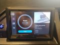
Touchscreen
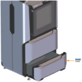
Storage Drawer
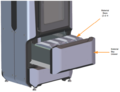
Material Bay Drawer
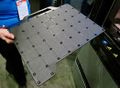
Build Plate
Material Spool


Training
Operation
The basic workflow for using the F370 will be as follows: Preparing the Printer, Preparing Your File for Print, Printing Your Part, Soaking Your Part. First, you prepare the printer so that it is physically ready to print any design you give it. Second, you prepare the part on the software used by the F370. This generates a file that tells the machine how to produce your part. Third, the machine prints your part. Fourth, you soak the part in the bath so that it dissolves all the support material. Then you have a finished part! Each section below will have specific information relevant to each step. You are encouraged to speak with a lab volunteer for advice and guidance for any step of the process. If you need to print a part for a class project make sure you get it added to the pack at least 3 days before it will be needed.
Demonstration
To show a complete knowledge of the F370, students will bring in a part, prepare it on the machine, print it, and soak it in the support bath.
General Procedure
- Preparing the F370
- Powering on the Printer
- The F370 can be powered on by pressing the large power button next to the touch screen console on the front of the printer. The printer may take up to 15 minutes to boot up, so do this step first if you plan to print soon.
- Before you can open your part in GrabCAD, make sure your part is in the .STL format.
- Acceptable Prints
- The maximum part size is 14 x 10 x 14 inches, or 35.56 x 25.4 x 35.56 centimeters, because that is how large the build plate is. Any part that is larger should be shown to a lab volunteer to discuss options.
- Generally, a part will be fit for the F370 if it is highly detailed and/or has holes that require fairly high tolerances. If it is a small, detailed part, a Form 2 printer should suffice. If the part is quick and simple, a Prusa will likely suffice.
- If your part is designed to take advantage of the dissolving support material the Stratasys machines use, then verify with a lab volunteer that it will be okay to print.
- Even if you are certain your part belongs on the F370, double check with a lab volunteer before you add it to the pack. Their goal is to help you, but the Prototype Lab would like to avoid excessively expensive and/or unnecessary prints.
- Powering on the Printer
- Preparing the file: GrabCAD
- GrabCAD Print is the software shared by both F370s. It allows one to easily orient and view the part that needs to be printed. Both printers are web based, which allows one to start the print from the one of the lab's computers. Give yourself a few days before your project is due to print on either F370. Prints will generally be started when a tray is full or by a lab volunteer at the end of a day. It is unlikely your print will be started just because you waited until the last minute. Be proactive.
- On Opening GrabCAD, make sure that you navigate to the bottom right of the screen and select the menu next to "Print." Select the printer you want to use; in this case, the F370, which will appear as "f370D30365". The volunteers in the lab can help you determine which printer would work best.
- To begin preparing your part, click on "Add Models". This is how you import your file into GrabCAD. Your file must be in .stl format. After you have added your part, you can begin preparing it to be printed. Multiple models can be added to the project. Additionally, models can be placed on new trays if the current one runs out of space.
- Notice that once a part has been added, an hourglass shaped tower will appear next to your part and scale with the size of your part. This is called a "purge tower" and is where a printer expels excess material upon switching filaments. The purge tower can be moved around on the plate as needed, but cannot be rotated. To move your part on the plate, one can simply click and drag to place it where they want to be printed. Keep in mind that the build plate is to scale, where you place it in the software will be where it prints in reality.
- To change how one is viewing the plate, hold on the middle mouse button and drag to move the plate, or click and hold the right mouse button to orient the angle the plate is viewed from. There are also icons on top to choose various viewpoints, such as an isometric view, top, left, etc. The icons on the right side of the screen are your print options. All of the options are intuitive, but you are still encouraged to practice manipulating your part so you understand how to use each function. The top three 'icons are different views, starting from a normal Model View, which is roughly how your part will appear when done.
- Analysis Mode shows faulty areas of a part, and Slice Preview shows model material and support material in the part. Below the Slice Preview Icon is the Model Info, where you can change the units of a selected part if needed.
- Next is Print Settings, which will be addressed below. The Arrange icon automatically arranges parts to optimize print time. Orient allows one to either let the software orient the part, orient a particular face to a plane, or rotate the model on the XYZ axis. Lastly, the Scale icon gives the option to change the size of the model, either with uniform scaling or on a particular axis. It also gives you the part dimension for each axis.
- You MUST print your part with "Sparse - low density" fill. It is expensive to print with Stratasys materials, thus you must consult a lab volunteer if you have a part you feel needs a denser fill. All of standard settings generally do not need to be changed.
- If you would like more information on specifics, head to the GrabCAD website's Help Center for further details and tips, guides, or answers to FAQs. This video contains a basic rundown of GrabCAD. Remember that the lab volunteers are available to answer your questions or provide assistance.
- ??
- Printing the part: F370 Touchscreen Operation
- After your part has been prepared, save the project before continuing. Generally, you will not start the print in the lab itself, since a volunteer will start it when a tray is full or when the day ends, but the workflow is as follows.
- Select "Print." The software will prepare the print. For larger packs, this may take several minutes, but usually takes around 30 seconds. If a print is currently ongoing, a bar across the top will read, "Print job queued successfully."
- Once your part has been prepared, you can click on on "View Estimates" in the bottom right-hand corner. You will see print time and the amount of model and support material that will be used, in cubic inches (in^3). This is an example of what the tray estimation page looks like. The model and support material used can be input into the Job Log in the lab.
- Touchscreen operation on the F370 is highly intuitive. In the image below, the four icons on the left are as follows:
- Home - Displays the current tray to be printed. If a print is in progress, it will display how much time is left in the print and what is being printed. After a few minutes, a screen saver will switch between displaying which layer is being printed and how much time is left on the current print.
- Queue - Shows which trays are queued. This can also be viewed in GrabCAD.
- Materials - Display which material trays contain material, what kind of material is in the F370, and how much material is left. It also displays tip temperature for each respective material.
- Tools - The last menu has various settings and functions for the printer. One of the icons in this menu will be a sun, which turns the light inside the printer on and off so a print can be viewed. Otherwise, do not mess with or change settings without speaking to a volunteer first.
- To start your print, the image above shows the home screen for the console. If a build plate is in place, the F370 has sufficient materials, and the correct tray is displayed, simply select "Print" and the print will begin.
- Soaking the part: Dissolvable Support Bath
- You will need to soak your finished part in the Dissolvable Support Bath in order to remove the support material. Much of it can be removed with pliers, but the remainder needs to be taken care of with the bath.
- For more information, see the Dissolvable Support Bath page. This section will contain basic information on what to do with the parts and bath, with basic safety info (gloves, goggles, washing yourself, spill, etc) and "see bath page for more detailed information" on particular topics.
- Build Plates
- F370 build plates are reusable, but when parts are removed from the plate, they often leave layers of support material that are extremely difficult to remove, rendering that part of the plate unusable. If a large pack or part is queued and a new plate is required for a print, go ahead and use a new plate. If a print or pack is smaller and can be printed without interference from unusable parts of a plate, try your best to reuse plates.


Safety
- When you are removing the support material by hand, it can be a little hot and sharp to begin with. Using a tool of some sort to chip it off is a good way to go, because hands bleed and tools don't :)
- When using the dissolvable support bath, do not use your bare hands to put your parts in! The liquid consists of water and Sodium Hydroxide which is a strong base! Use goggles, a lab coat, and the huge thick rubber gloves so that you don't get any on you.
Approved Filaments
Certification
Troubleshooting
- If GrabCAD says printer isn't available, then it is not started up. Make sure the printer has been on for a while so it can connect to the network appropriately.
- It may take a while to start the print if your printer was just recently used. It can take 2 hours to heat up before the printing the job begins.
- Make sure you have enough material in the material bay to complete the print before you begin.
Maintenance
General maintenance
There are a few things students and the ace will need to do while performing maintenance tasks or the F370.
Specific Maintenance Tasks
| Maintenance Procedure | Frequency | Done By |
|---|---|---|
| Changing Materials | When the amount of material gets low | Volunteer |
| Removing Material from Build Plate | After every print | Student |
- Changing Materials (Loading Filament Spools)
- Only volunteers will change out materials. If the F370 runs out of filament or you would like to use a different color, please speak to a lab volunteer.
- There are four material bays within the F370. The top drawer houses the material bays and their material drive controller, which feeds the filament from the bay to the head. The material drive controller detects whether material is in the material drive during the load and unload process and it can also detect errors, when filament is broken, or when the end of the spool is reached via a filament present switch. [This sentence needs to be revised by someone that understands the details of the "material drive] [I gave it a try, probably needs an expert to review - CZ] The print will be paused if any of these things occur so the print can be recovered and filament reloaded.
- Select the Materials button from the touchscreen.
- Open the material bay drawer. That is the biggest drawer on the bottom half of the F370.
- Insert the material spool into its appropriate slot. In the Prototype Lab, the two bays on the left will contain model material, while the bays on the right will contain support material.
- Pull up on the latch securing the lid and open the lid.
- Place the material spool into the slot. Make sure the filament tail is facing the back wall of the material bay (printer side).
- Once the spool is inserted, the Material Status icon will display a solid yellow border with a notification badge above the icon.
- Open the Materials Details page by tapping on the status icon for the bay you are loading material into.
- Slowly turn the spool and feed filament through the filament hole.
- The filament needs to be advanced approximately 2 inches to reach the filament present switch. When the switch is reached, the Load button will refresh into a selectable state.
- When feeding filament, be careful to ensure that filament does not fall over the edge of the spool to avoid cross-winding and/or load errors.
- Once the filament present switch detects filament, select the Load icon.
- Press the Back button within the Material Details page to exit and return to the Materials page.
- Material will begin to load and the F370 will take care of the rest, automatically heating both the oven and liquefier tip to the correct temperatures for the material being used.
- Once the tip is within three degrees of the set point temperature the head moves to the purge area and the tip purges a small amount of material.
- Once material is loaded, the filament pathway between the Material Status Icon and the corresponding Head Status Icon will be solid blue, the Head Status Icon will turn from gray to blue, and the Material Status Icon will display a solid blue border.