Difference between revisions of "Electronic keyboard"
| Line 85: | Line 85: | ||
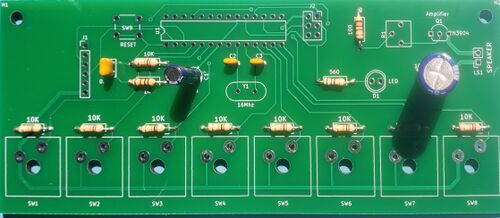
Electrolytic capacitors are polarized, which means that they need to be connected the right direction. Match the side of the part with the stripe with the white side of the circle on the board. | Electrolytic capacitors are polarized, which means that they need to be connected the right direction. Match the side of the part with the stripe with the white side of the circle on the board. | ||
| − | [[Image: | + | [[Image:board_with_electrolytic_.jpg|500px]] |
Revision as of 16:41, 8 June 2021
In this TV, we will be creating an electronic keyboard.
Bill of Materials
- Keyboard PCB
- Keyboard parts kit
- printed keyboard caps
- Solder
CAD
My paragraph
For this TV, the cad has been done for you, as this is more of an exercise in assembly and programming than in design.
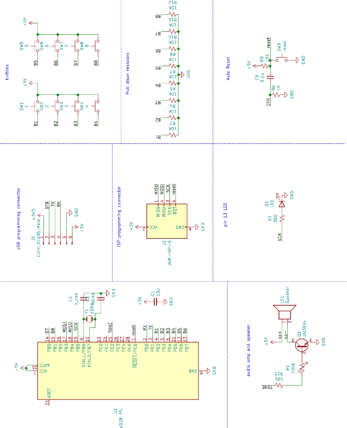
Here is the Schematic used for this build:
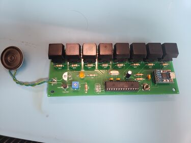
The processor is an ATmega328, the same processor as is used on the Arduino Uno. There are 8 button inputs, with pulldown resistors on the signal lines, and a speaker amplifier to drive a small speaker.
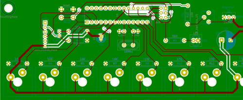
This schematic was used to create the following PCB:
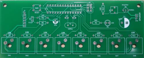
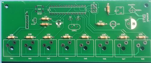
The cad file is sent to a manufacturer, and they send back a board that looks like this:
Using this board, we will assemble the circuit. This build makes heavy use of soldering, so check out the soldering wiki page: INSERT
ASSEMBLY
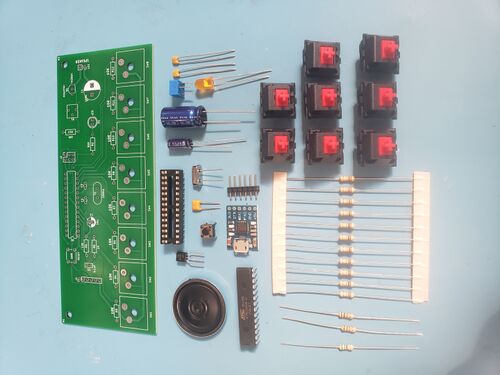
parts:
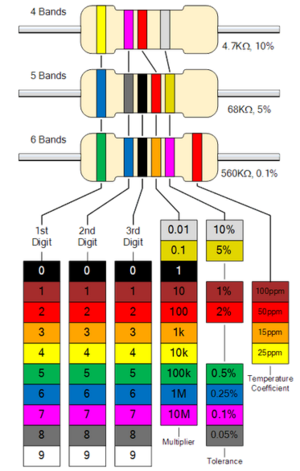
To start off, let's solder the resistors. There are 4 resistor values used on the board; 10,000 ohms (10K), 1,000 ohms (1K), 100 ohms (100), and 560 ohms (560). The resistor values are coded by colored stripes on the side of the resistor; the following chart describes this code:
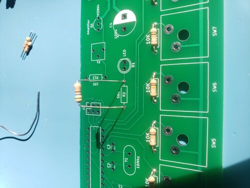
To solder the resistors, first bend the legs over, and thread the wires through the holes in the board.
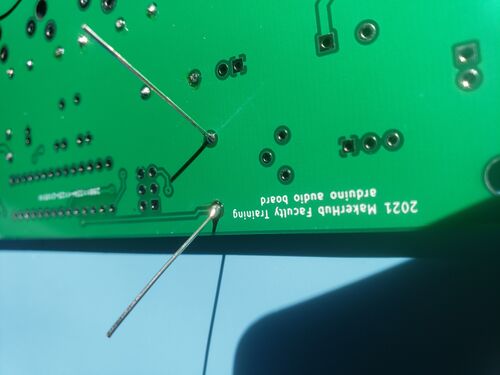
on the back, bend them out a little to hold it in place, and then solder the connections.
Then, clip the leads back to the top of the solder joint
Repeat for all resistors.
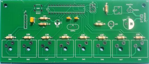
Next, let's solder the ceramic capacitors. they are the small 2 leaded yellow parts.
The larger one is a 0.1uF value, and the 2 smaller ones are 18pF.
next, there is 1 electrolytic capacitor to add. The larger one on the right isn't used in this version of the circuit. Electrolytic capacitors are polarized, which means that they need to be connected the right direction. Match the side of the part with the stripe with the white side of the circle on the board.
